Aug 31, 2026
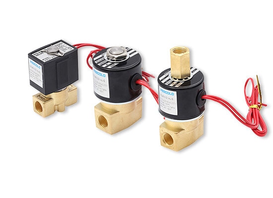
Solenoid valves are widely used in automated fluid and pneumatic systems because they allow electrical signals to control the movement of air, water, steam, and other compatible media. Their compact construction, relatively fast switching, and integration with control circuits make them suitable for equipment ranging from simple machinery to complex production lines.
As automation develops, solenoid valves are increasingly combined with valve manifolds, sensors, PLCs, and remote monitoring systems. However, their functions vary according to internal structure, port configuration, operating pressure, and media compatibility. Understanding these differences helps engineers select the right valve for each application.
A solenoid valve is an electromechanical device that uses an energized coil to operate an internal plunger or pilot mechanism. This movement changes the valve's flow path, allowing the valve to start, stop, or redirect a medium.
Solenoid valves are commonly used in industrial automation, HVAC equipment, medical devices, water treatment, irrigation, and pneumatic machinery. Depending on the design, they can control gases or liquids, including compressed air, water, oil, and steam.
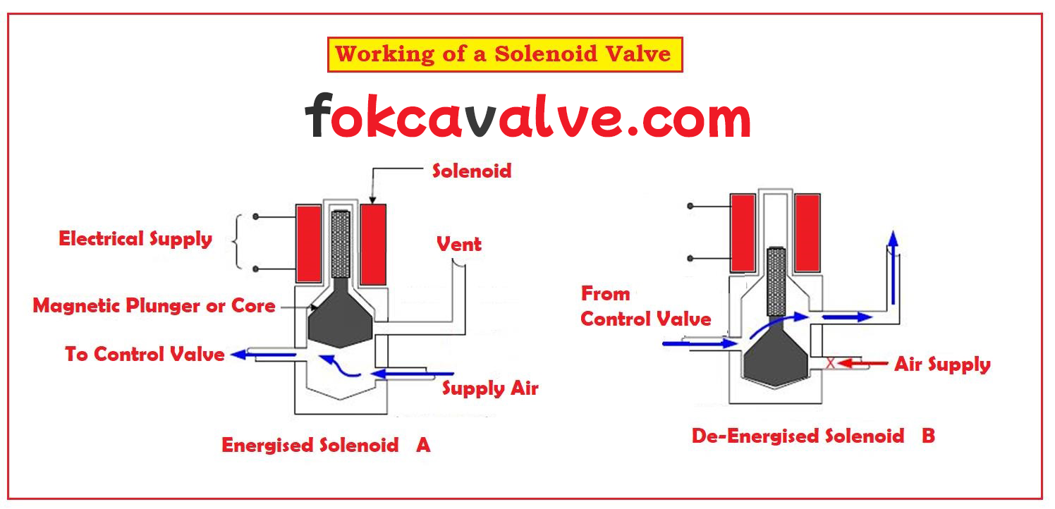
A typical solenoid valve consists of four main components:
● Solenoid coil: Generates a magnetic field when electrical power is applied.
● Plunger or armature: Moves in response to the magnetic force.
● Spring: Returns the moving element to its default position in spring-return designs.
● Valve body and seat: Form the internal flow passages and sealing surfaces.
When the coil receives the specified voltage, its magnetic field attracts the plunger. The resulting movement opens or closes a passage, or operates a pilot stage that controls the main valve element.
When electrical power is removed, the spring or another return mechanism moves the valve back to its default position. In a double-solenoid or latching design, the switching behavior may differ, so the control method must be checked against the manufacturer's specifications.
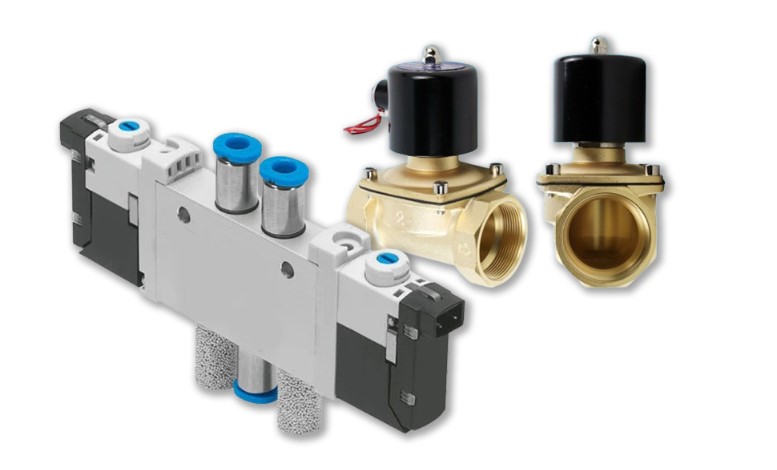
Solenoid valves can be grouped according to the medium they control, their pressure range, actuator application, and internal configuration.
| Valve type | Typical applications |
| Gas solenoid valve | Compressed air, nitrogen, and other compatible gases |
| Water solenoid valve | Water supply, irrigation, and liquid distribution |
| Steam solenoid valve | Steam equipment and heating systems requiring suitable high-temperature materials |
Material selection is important. The valve body, internal components, and seals must all be compatible with the medium, temperature, and operating pressure.
Solenoid valves are also selected according to their permitted operating pressure:
● Low-pressure models: Used in applications with relatively low system pressure, such as certain pneumatic and water-control circuits.
● Medium-pressure models: Designed for general industrial systems within their specified pressure range.
● High-pressure models: Built for applications involving higher fluid pressure, with suitable body construction, sealing, and internal components.
There is no universal pressure boundary separating these categories. Always refer to the specific model's rated pressure and operating conditions.
In automated equipment, solenoid valves commonly serve as control elements for different actuators:
● Pneumatic actuators: Direct compressed air to pneumatic cylinders and rotary actuators.
● Hydraulic actuators: Control hydraulic fluid flow to hydraulic cylinders or motors when the valve is designed for hydraulic service.
● Pneumatic clamps: Operate clamping mechanisms used in assembly and positioning systems.
● Motorized valve assemblies: Solenoid valves may provide pilot air or hydraulic control for actuated ball, butterfly, or other process valves.
The solenoid valve controls the fluid circuit; the actuator converts that fluid energy into mechanical movement.
Directional solenoid valves are commonly identified by the number of ports and switching positions.
| Configuration | Ports and positions | Typical application |
| 2/2-way | 2 ports, 2 positions | Basic flow on/off control |
| 3/2-way | 3 ports, 2 positions | Single-acting cylinder control |
| 4/2-way | 4 ports, 2 positions | Directional control of double-acting actuators |
| 5/2-way | 5 ports, 2 positions | Commonly used with double-acting pneumatic cylinders |
| 5/3-way | 5 ports, 3 positions | Directional control with different center-position functions |
The center position of a 5/3-way valve may be closed, pressure, or exhaust, depending on the design. This affects how the actuator behaves when the valve is in its neutral state.
Other specialized designs include direct-acting, pilot-operated, and NAMUR-mounted solenoid valves. Their suitability depends on flow requirements, operating pressure, installation method, and control arrangement.
When a pneumatic solenoid valve fails to switch correctly, a systematic inspection can help identify the cause.
● Visual inspection: Look for cracks, corrosion, damaged connectors, loose fittings, and signs of air leakage. Check whether the valve and tubing are securely installed.
● Electrical testing: Confirm that the supply voltage and control signal match the coil specifications. A multimeter can be used to measure coil resistance and identify possible open or short circuits. Disconnect power before resistance testing.
● Manual and switching checks: If the valve has a manual override, use it according to the manufacturer's instructions to check whether the spool or internal mechanism can move. Isolate the system where necessary before testing.
● Airflow inspection: Verify that the supply pressure is within the specified range and that the inlet, outlet, and exhaust passages are not blocked. Check whether the valve changes flow paths correctly.
● Operating response: Energize and de-energize the valve under controlled conditions. Observe switching behavior, abnormal noise, leakage, and delayed response. A clicking sound alone does not prove that the valve is functioning correctly.
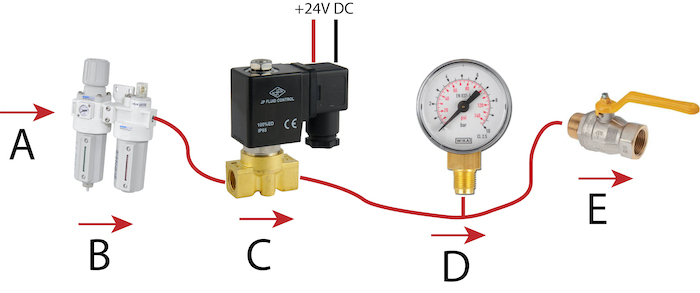
Before removing or servicing a pneumatic solenoid valve, disconnect the electrical supply and isolate and depressurize the air circuit. If the valve still fails to operate, inspect the control signal, air supply, internal contamination, seals, and spool condition.
Solenoid valve selection should always account for the medium, pressure, temperature, electrical specifications, port configuration, and required flow capacity. Matching these factors to the actual operating conditions helps ensure reliable switching and stable performance in industrial automation systems.
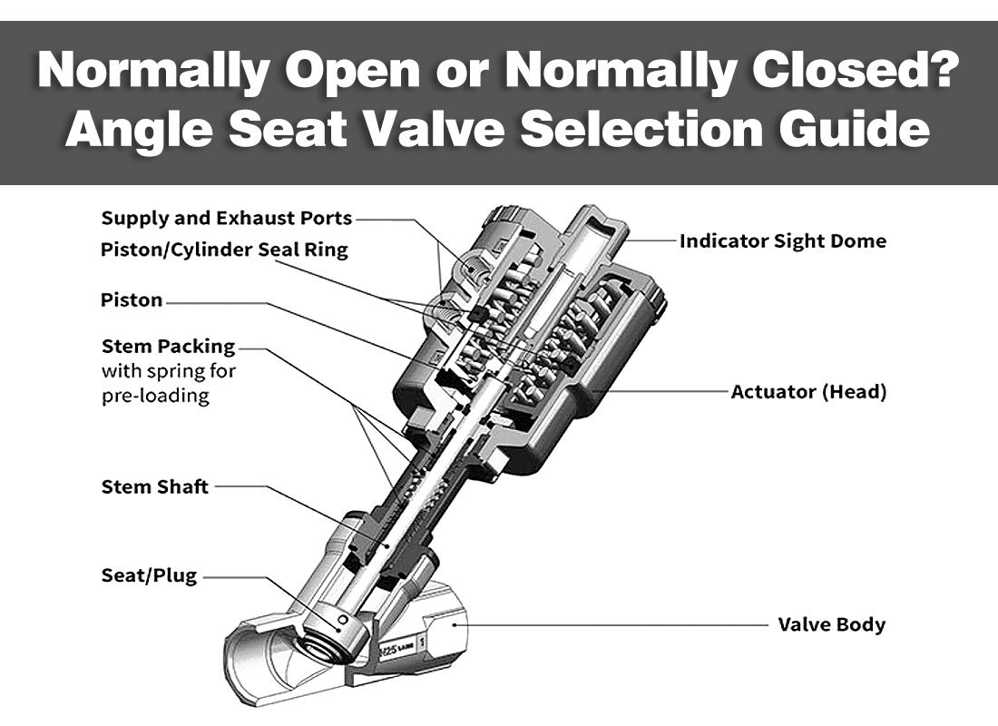 Normally Open or Normally Closed? Angle Seat Valve Selection Guide
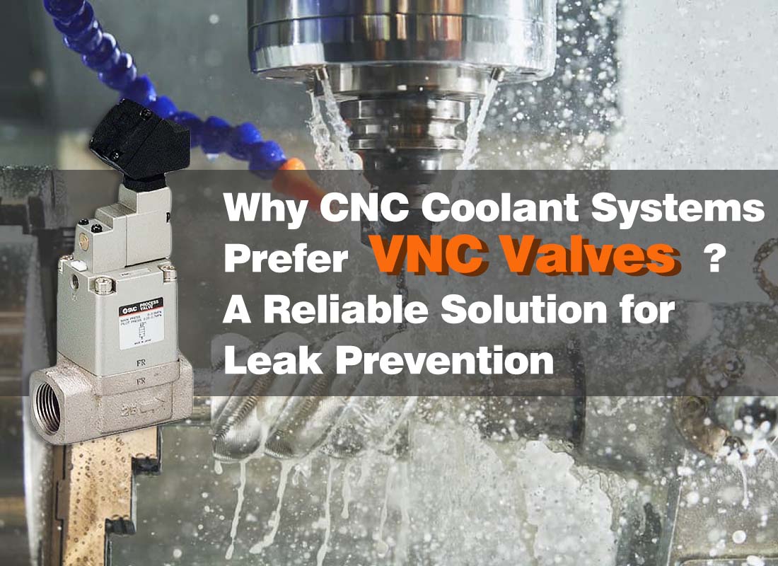 Why CNC Coolant Systems Prefer VNC Valves? A Reliable Solution for Leak Prevention
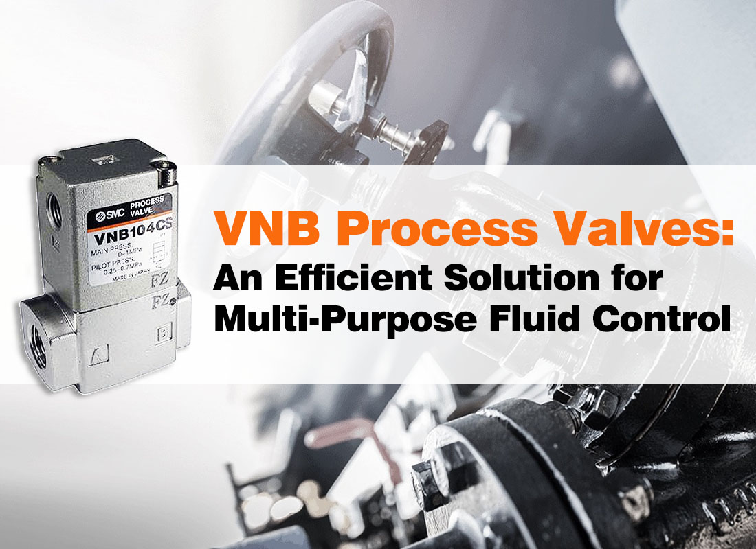 VNB Process Valves: An Efficient Solution for Multi-Purpose Fluid Control
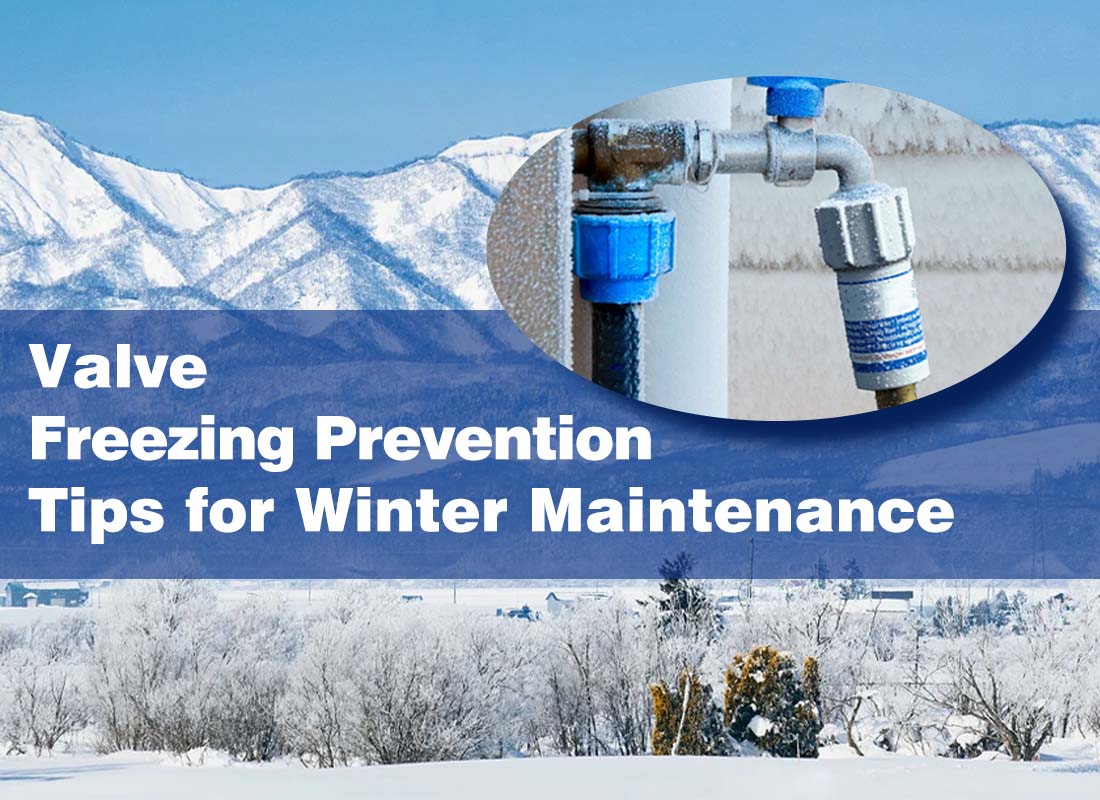 Valve Freezing Prevention Tips for Winter Maintenance
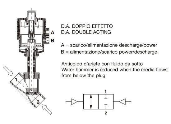 How to determine valve seat angle
You May Interest In

Dec 02, 2025 Blog
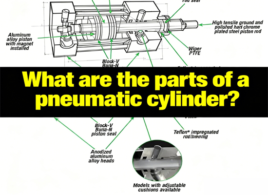
What are the parts of a pneumatic cylinder?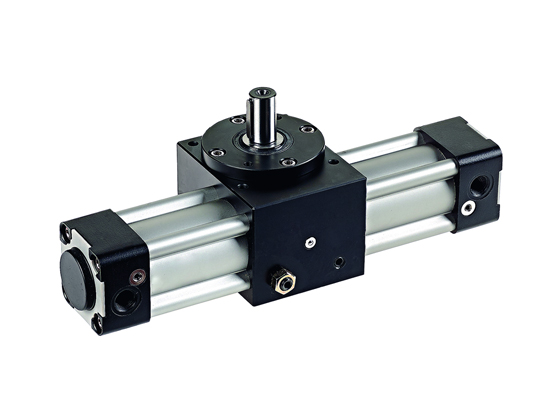
Apr 18, 2025 Blog
What is an Angle Seat Valve?
Get a free sample

Fokca is a brand of Ningbo Fokca Automation Co., Ltd.
Looking for custom pneumatic cylinder solutions? Visit our sister brand, Fescolo.→
© 2026 Ningbo Fokca Automation Co., Ltd. All rights reserved. Sitemap