Sep 03, 2026
The valve seat angle is an important geometric feature that affects how a valve closes, seals, and controls fluid flow. Even a small deviation from the specified angle can change the contact area between the sealing surfaces, potentially causing leakage, uneven wear, or reduced operating efficiency.
Valve seat geometry varies considerably between applications. Engine intake and exhaust valves, pneumatic angle seat valves, and industrial process valves do not necessarily share the same seat design or reference angle. Therefore, determining the correct angle requires understanding the valve structure, identifying the relevant reference surface, and selecting an appropriate measuring method.
For maintenance technicians, machinists, and quality inspection teams, accurate measurement helps verify manufacturing tolerances, diagnose sealing problems, and maintain consistent valve performance.
The angle of a valve seat determines how the valve disc or sealing surface contacts its mating component. When the two surfaces are designed to match correctly, they can form a stable sealing interface under the specified operating conditions.
An incorrect angle may produce an excessively narrow contact band, uneven pressure distribution, or incomplete contact. These conditions can lead to internal leakage and accelerate wear during repeated opening and closing cycles.
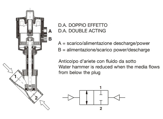
Seat geometry also influences the available flow passage. In engine valves, for example, the valve opening changes continuously as the valve lifts from its seat. The clearance between the valve face and seat therefore plays an important role in controlling gas flow, particularly during the early and late stages of valve movement.
In industrial valves, the effect depends on the design. Seat angle, opening travel, flow direction, pressure differential, and internal passage geometry work together to determine flow characteristics and sealing performance.
Several angles are used in valve manufacturing, including 30°, 45°, 60°, and 75°. However, these values are not interchangeable standards for every valve type.
| Seat angle | Typical context | Main consideration |
| 30° | Certain engine intake valve designs | Can provide favorable flow characteristics |
| 45° | Common engine valve seating design | Balances sealing contact and flow geometry |
| 60° | Some specialized valve and seat designs | Used when specified by the design requirements |
| 75° | Certain multi-angle machining profiles | Often forms part of a compound seat geometry |
In engine applications, a 45° seating face is widely used, while some intake valve designs use 30°. Multi-angle machining may also combine several adjacent surfaces to improve airflow and control the contact area.
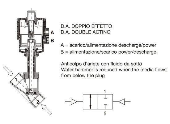
For pneumatic angle seat valves and industrial control valves, the seat angle is determined by the manufacturer's design. It should not be assumed to be 45° simply because that angle is common in engine applications.
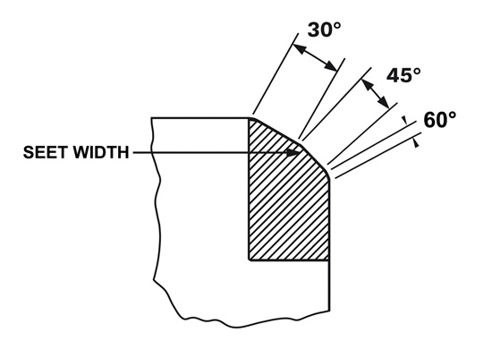
The appropriate measurement method depends on the valve's size, construction, required tolerance, and inspection environment. The following approaches cover common workshop and manufacturing situations.
A dedicated valve seat gauge is useful for engine rebuilding, machining, and routine workshop inspection.
First, remove dirt, oil, and carbon deposits from the valve face and seat. Secure the component in a stable fixture, then position the gauge against the specified reference surface. Adjust the tool until it sits correctly and read the angle indicator.
This method is convenient for repeated measurements, but the gauge must match the valve geometry and be properly calibrated. Incorrect positioning can produce misleading readings.
For basic inspection, a protractor or digital angle finder can provide an approximate measurement.
Secure the valve without damaging its stem or sealing face. Align the measuring instrument with the reference axis, then position its measuring edge against the valve face. Read the displayed angle and compare it with the specified drawing.
This approach is suitable for preliminary checks, but it may not provide sufficient accuracy for precision machining. A small alignment error can significantly affect the result, especially on narrow seating surfaces.
For standardized industrial valves and OEM components, the product drawing, technical manual, or manufacturing specification should be the first reference.
Check whether the specified angle refers to the valve disc, valve seat, sealing face, or another geometric feature. Some designs use compound angles or special sealing profiles, so a single nominal angle may not describe the complete geometry.
This method avoids unnecessary disassembly and provides the intended design value. However, it does not confirm that a used or manufactured component actually meets the specification.
A profile projector or optical comparator is suitable for precision inspection in machining workshops and quality control departments.
Place the cleaned component on the measuring stage and align its profile with the optical system. Focus the projected outline, establish the correct reference axis, and compare the seating surface with the instrument's angular scale.
Optical measurement is particularly useful for small components, narrow sealing faces, and compound seat profiles. Accuracy depends on equipment calibration, fixture alignment, and the operator's measurement procedure.
A contact pattern test helps determine whether the valve face and seat make uniform contact. It is not a direct method for measuring the actual angle.
Apply a thin layer of marking dye to the relevant surface, then bring the mating components together using the appropriate inspection procedure. For compatible engine valve assemblies, light lapping may be used when permitted by the manufacturer's instructions.
An even contact band indicates more consistent contact. A patch concentrated on one edge may suggest an angle mismatch, surface distortion, or alignment problem. Contact appearance alone cannot identify the exact angular deviation.
A mismatch between the valve face and seat can produce several warning signs:
● Internal leakage or failure to maintain pressure
● Uneven or excessively narrow contact marks
● Wear concentrated on one side of the sealing surface
● Reduced engine compression in combustion engines
● Abnormal operating temperature or accelerated seat deterioration
● Inconsistent valve closing performance
These symptoms can also result from damaged surfaces, contamination, incorrect alignment, or insufficient closing force. The seat angle should therefore be checked alongside other possible causes.
| Application | Angle selection |
| Engine intake valves | Often 30° or 45°, depending on engine design |
| Engine exhaust valves | Frequently 45°, subject to manufacturer specifications |
| Pneumatic angle seat valves | Defined by the valve's internal sealing geometry |
| Industrial process valves | Depends on valve type, pressure, medium, and design |
| High-pressure and steam valves | Must follow the specified design and applicable standards |
There is no universal rule that higher-pressure valves always require a larger seat angle. Material strength, sealing structure, temperature, pressure differential, and operating conditions all influence the final design.
A 45° seat is widely used in engine valve designs. However, other angles are common in specific applications, and industrial valves follow their own design specifications.
The mating surfaces may not contact properly, resulting in leakage, uneven wear, reduced sealing performance, or abnormal operation.
Yes. A protractor or digital angle finder can provide an approximate measurement. Precision inspection generally requires suitable gauges or optical equipment.
No. Their sealing geometry varies by manufacturer, valve structure, and operating requirements. Always refer to the product drawing or technical documentation before measuring or machining the seat.
(FK9026)
 Normally Open or Normally Closed? Angle Seat Valve Selection Guide
 Why CNC Coolant Systems Prefer VNC Valves? A Reliable Solution for Leak Prevention
 VNB Process Valves: An Efficient Solution for Multi-Purpose Fluid Control
 Valve Freezing Prevention Tips for Winter Maintenance
 How to determine valve seat angle
You May Interest In

Dec 02, 2025 Blog
What are the parts of a pneumatic cylinder?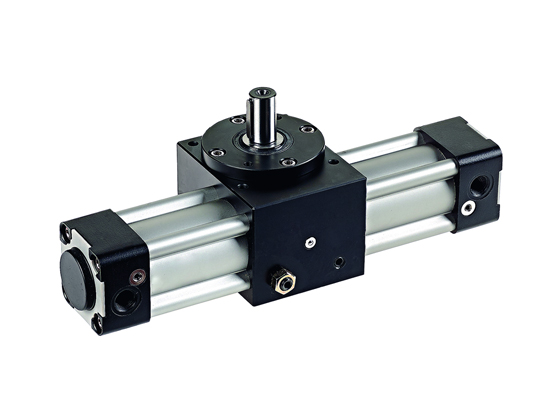




Apr 18, 2025 Blog
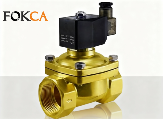
What is an Angle Seat Valve?
Get a free sample

Fokca is a brand of Ningbo Fokca Automation Co., Ltd.
Looking for custom pneumatic cylinder solutions? Visit our sister brand, Fescolo.→
© 2026 Ningbo Fokca Automation Co., Ltd. All rights reserved. Sitemap