Aug 31, 2026
Solenoid valves play an important role in automated fluid and pneumatic systems. By converting electrical signals into mechanical movement, they control the flow or direction of air, water, oil, and other compatible media. A malfunctioning valve may cause actuator delays, pressure loss, leakage, or unexpected equipment shutdowns.
Regular inspection helps identify electrical and mechanical problems before they affect the entire system. A practical check should cover the valve's external condition, coil, control signal, switching performance, sealing, and internal flow passages.
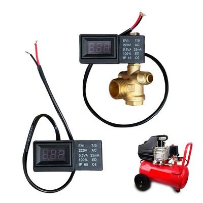
Begin by checking the valve without disassembling it. Look for:
● Cracks, deformation, corrosion, or other damage to the valve body.
● Oil, moisture, dust, or foreign material around the housing.
● Loose coils, connectors, plugs, and wiring terminals.
● Damaged seals or visible leakage around pipeline connections.
● Incorrect model numbers, voltage labels, or installation orientation.
A deformed housing may interfere with internal movement, while loose electrical connections can cause intermittent operation. External contamination may also affect connectors and contribute to electrical faults.
A multimeter can help determine whether the coil has an electrical fault.
First, disconnect the power supply and isolate the valve. If practical, remove the coil according to the manufacturer's instructions. Set the multimeter to resistance mode and measure across the coil terminals.
● Zero or unusually low resistance: May indicate a short circuit.
● Infinite resistance or OL: Usually indicates an open circuit.
● Abnormal resistance: Compare the reading with the manufacturer's specified value.
Coil resistance varies with voltage, design, and rated power, so there is no universal normal resistance range.
A functional test can also be performed using the correct rated power supply. A clicking sound may indicate armature movement, but it does not confirm that the valve switches properly. Never apply an incorrect voltage or energize a coil beyond its rated duty cycle.
If the coil appears normal but the valve does not respond, inspect the control circuit.
Check whether the PLC or controller supplies the specified voltage, whether terminals and plugs are secure, and whether the DC polarity is correct when required by the coil or connector design.
A multimeter can measure supply voltage at the coil terminals. An oscilloscope may help diagnose intermittent or pulse-based signals. Always follow electrical safety procedures when testing an energized circuit.
Restore the required operating conditions and observe the valve during energizing and de-energizing.
Check whether:
● The valve changes its flow path as expected.
● The connected cylinder or actuator responds correctly.
● Switching is consistent without sticking or unusual noise.
● The valve returns to its specified default state.
For pilot-operated valves, confirm that the minimum operating pressure or differential pressure is available. Insufficient pressure may prevent the main valve element from switching even when the coil operates normally.
Inspect both external and internal leakage.
For pneumatic systems, an approved leak-detection solution can be applied to external joints. Continuous bubbling indicates a possible leak. Internal leakage may be identified through unexpected pressure loss, continuous exhaust, or failure to maintain the required actuator position.
Check that the inlet, outlet, and exhaust passages are unobstructed. Internal filters, small orifices, and valve seats can become contaminated by dust, oil residue, or other particles.
A pressure gauge or flow meter can help evaluate operating performance. Compare measurements with the system's normal values and the valve manufacturer's specifications.
| Maintenance task | Purpose |
| Clean external surfaces | Prevent contamination around the coil and connectors |
| Inspect internal components | Identify dirt, wear, or damaged sliding parts |
| Check coil condition | Detect electrical deterioration or failure |
| Examine seals and O-rings | Identify cracks, deformation, and aging |
| Tighten electrical connections | Reduce the risk of poor contact |
| Check springs and valve elements | Ensure reliable switching and resetting |
Common replacement parts include solenoid coils, valve spool assemblies, sealing rings, O-rings, connectors, cables, and return springs. Use compatible replacement components specified for the valve model.
Before disassembly, disconnect electrical power, isolate the medium supply, and release residual pressure. Internal cleaning and component replacement should follow the manufacturer's maintenance instructions.
A systematic inspection makes it easier to distinguish electrical faults, insufficient operating pressure, mechanical sticking, and sealing problems. Checking these factors together helps restore reliable valve operation and reduces unnecessary component replacement.
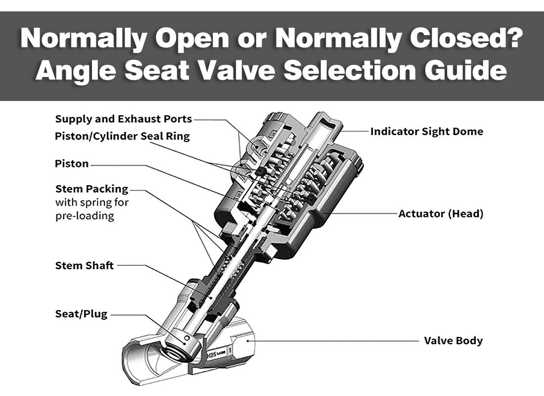 Normally Open or Normally Closed? Angle Seat Valve Selection Guide
 Why CNC Coolant Systems Prefer VNC Valves? A Reliable Solution for Leak Prevention
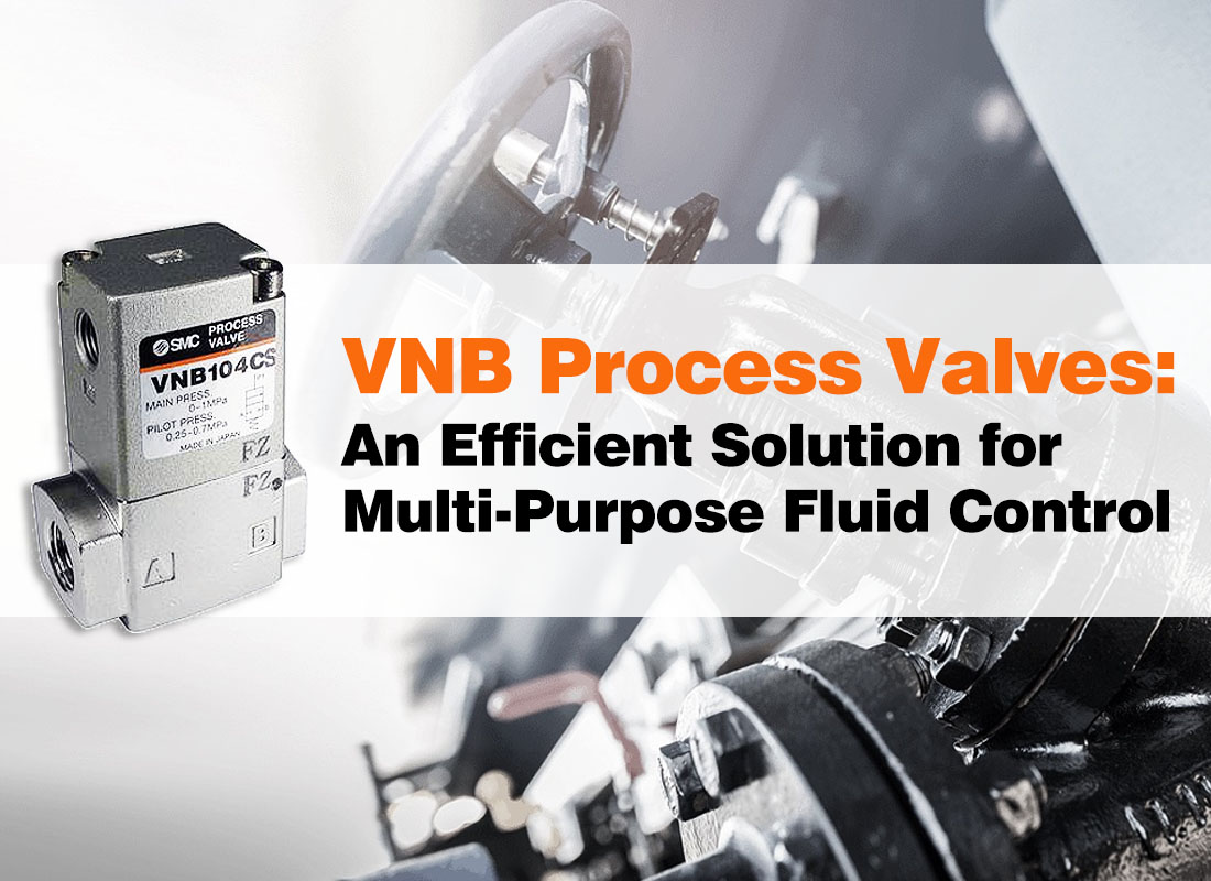 VNB Process Valves: An Efficient Solution for Multi-Purpose Fluid Control
 Valve Freezing Prevention Tips for Winter Maintenance
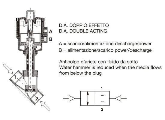 How to determine valve seat angle
You May Interest In

Dec 02, 2025 Blog
What are the parts of a pneumatic cylinder?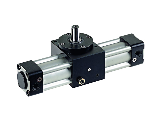


Apr 18, 2025 Blog
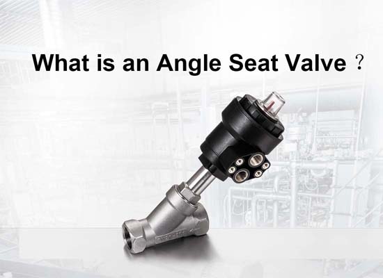
What is an Angle Seat Valve?
Get a free sample

Fokca is a brand of Ningbo Fokca Automation Co., Ltd.
Looking for custom pneumatic cylinder solutions? Visit our sister brand, Fescolo.→
© 2026 Ningbo Fokca Automation Co., Ltd. All rights reserved. Sitemap