Sep 30, 2026
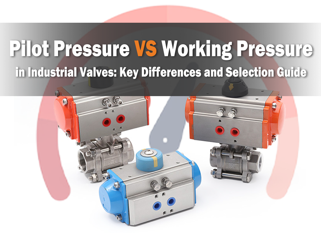
When selecting a pneumatic industrial valve, two pressure values often appear in the technical datasheet: pilot pressure and working pressure. Although both are expressed in units such as bar or MPa, they describe completely different operating conditions.
Pilot pressure supplies the force required to operate the actuator, while working pressure refers to the pressure of the process medium inside the valve and piping system. Confusing these two parameters can lead to insufficient actuator force, leakage, unstable switching, or damage to components.
Understanding how they interact is essential when selecting pneumatic valves for industrial automation, process equipment, and fluid-control systems.
The most important distinction is where each pressure acts and what function it performs.
Pilot pressure, also called control or actuator pressure, is the compressed-air pressure supplied to a pneumatic actuator. When air enters the actuator chamber, it creates a force that moves the piston, diaphragm, stem, or other valve operating element.
For a simple pneumatic actuator, the theoretical force can be expressed as:
F = P × A
where F is actuator force, P is pilot pressure, and A is the effective actuator area.
For example, an actuator with an effective area of 50 cm² supplied with 6 bar of air has a theoretical force of approximately 3,000 N, before accounting for spring force, friction, pressure losses, and other design factors.
This does not mean that every valve will operate correctly at 6 bar. The actuator must generate enough force to overcome the resistance created by the valve and process conditions.
If pilot pressure is too low, the valve may open or close slowly, fail to reach its end position, or become unstable. If it exceeds the actuator's specified maximum pressure, the actuator housing, piston, diaphragm, seals, or other components may be overstressed.
The correct pilot-pressure range should therefore always be taken from the specific actuator or valve manufacturer's datasheet, rather than from a general industry value.
Working pressure is the pressure of the medium being controlled by the valve. Depending on the application, this could be water, compressed air, steam, oil, chemicals, or another process fluid.
Unlike pilot pressure, working pressure acts on the valve body, seat, sealing elements, and internal components. The valve must be designed to withstand this pressure under the specified operating temperature and medium conditions.
For example, a valve with a rated working pressure of 1.6 MPa should not be selected for an application where the process pressure continuously exceeds that rating. The actual allowable pressure may also decrease at elevated temperatures, depending on the valve material and design.
Therefore, the working-pressure rating should always be checked together with temperature, medium compatibility, valve size, connection type, and applicable pressure standard.
Although the two pressures are different, they are not completely independent.
The process pressure can create a force that the actuator must overcome. This is particularly important for valves with large nominal sizes, high differential pressure, or designs where the medium pressure acts strongly against the closing or opening direction.
The required actuator force can therefore be affected by:
● Differential pressure across the valve
● Valve seat design and sealing force
● Valve size and effective flow area
● Medium characteristics
● Actuator type and spring force
● Friction and mechanical resistance
● Required safety margin
This is why simply confirming that the pilot pressure is within the actuator's rated range is not enough. The actuator must also have sufficient available force or torque for the actual valve operating conditions.
The original assumption that actuator material or diameter alone determines its maximum pilot pressure is too simplistic. In practice, the allowable pressure is determined by the complete actuator design, including housing geometry, wall thickness, seals, piston or diaphragm construction, connection method, temperature, and safety requirements.
Actuator diameter has an important effect on output force because the effective area increases with diameter.
For a circular piston:
A = πD² / 4
This means that increasing the piston diameter can significantly increase the available force at the same pilot pressure.
However, a larger actuator does not automatically have a higher allowable pilot pressure. The housing and internal components must be designed to withstand the corresponding internal loads.
For this reason, actuator manufacturers normally specify both a recommended operating pressure range and a maximum allowable pressure for each model.
Plastic actuator housings, aluminum housings, and stainless steel housings can have different mechanical and environmental characteristics. Stainless steel may be preferred in corrosive, washdown, or hygienic environments, while engineered plastics or aluminum may be suitable for lighter applications.
However, material alone should not be used to determine the pressure limit. Two actuators made from the same material can have different pressure ratings because of differences in geometry, sealing design, manufacturing process, and safety factor.
When selecting a pneumatic industrial valve, check the pressure parameters in the following order:
Determine the normal and maximum working pressure, temperature, medium, and differential pressure.
Make sure the valve body, seat, seals, and connections are suitable for the actual process conditions.
Consider differential pressure, valve size, seat design, and the force required to move the valve.
Confirm that the available compressed-air pressure falls within the actuator's specified operating range and that sufficient output force is available.
Do not assume that two actuators of the same diameter or material have identical pressure ratings.
Pilot pressure and working pressure describe two different sides of valve operation. Pilot pressure provides the energy needed to move the actuator, while working pressure describes the process conditions that the valve body and internal components must withstand.
Reliable selection requires both parameters to be evaluated together. A valve may have an adequate pressure rating for the process medium but still fail to operate if the actuator does not receive sufficient pilot pressure. Conversely, an actuator may operate correctly while the valve body is unsuitable for the process pressure or temperature.
For pneumatic valves, the most reliable approach is to match the valve pressure rating, actuator output, pilot-pressure range, and actual process conditions against the manufacturer's technical data before installation. This prevents undersized actuators, reduces leakage and operating problems, and provides a more dependable valve system over its service life.
(FK9025)
 Pilot Pressure vs Working Pressure in Industrial Valves: Key Differences and Selection Guide
 Water Hammer Explained: Why Angle Seat Valves Are the Optimal Solution
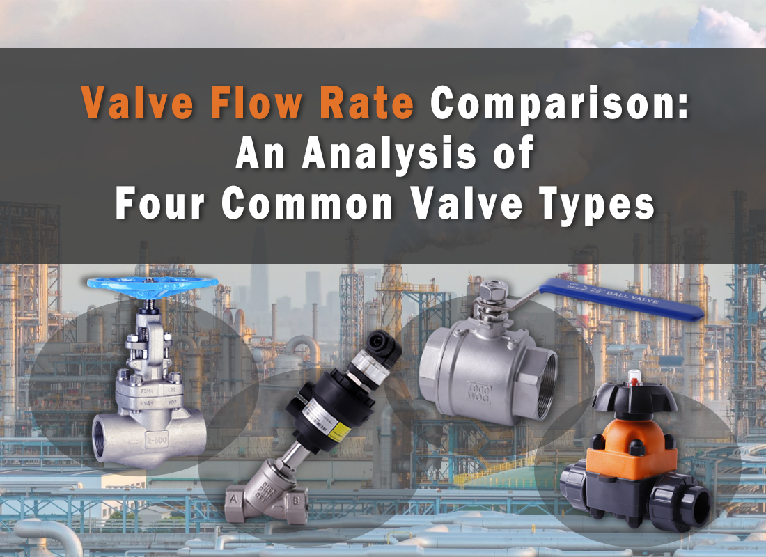 Valve Flow Rate Comparison: An Analysis of Four Common Valve Types
 The Temperature Limit of Valves: How Seal Material Affects Valve Body Performance
 Valve Flow Coefficients CV & KV: Differences Analysis and Selection Guide
You May Interest In


Dec 02, 2025 Blog
What are the parts of a pneumatic cylinder?


Apr 18, 2025 Blog
What is an Angle Seat Valve?
Get a free sample

Fokca is a brand of Ningbo Fokca Automation Co., Ltd.
Looking for custom pneumatic cylinder solutions? Visit our sister brand, Fescolo.→
© 2026 Ningbo Fokca Automation Co., Ltd. All rights reserved. Sitemap




 None
None