Sep 01, 2026
A solenoid valve manifold is a centralized pneumatic assembly that combines multiple solenoid valves on a common base. Instead of installing each valve separately and connecting individual air supply lines, the manifold distributes compressed air through integrated internal passages to several valve stations.
Each valve controls a separate pneumatic circuit, allowing multiple cylinders, grippers, or other actuators to operate independently or in coordination. By consolidating air connections and electrical interfaces, a solenoid valve manifold simplifies system layout, reduces installation work, and makes maintenance more convenient.
Manifolds are widely used in automated equipment where multiple pneumatic movements must be controlled within a limited space.
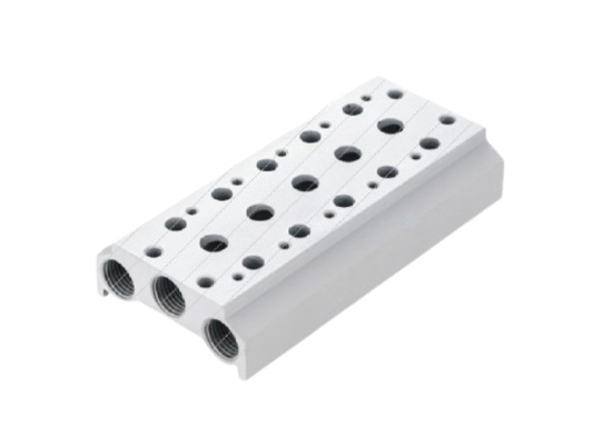
The main advantage of a manifold is the integration of multiple control points into one assembly. Its design offers several practical benefits:
| Feature | Function and Benefit |
| Centralized air supply | Distributes compressed air to multiple valve stations through internal passages |
| Independent valve control | Allows individual actuators to operate according to separate control signals |
| Integrated exhaust | Consolidates exhaust connections where the manifold design permits |
| Simplified wiring | Reduces individual cable routing through centralized connectors or wiring modules |
| Modular construction | Supports maintenance, replacement, and configuration changes within design limits |
Depending on the model, valve manifolds may support different valve functions, station numbers, connector types, and communication options. Modular designs are particularly useful when production equipment needs to accommodate additional pneumatic functions or undergo frequent configuration changes.
A manifold system operates by combining compressed-air distribution, electromagnetic valve switching, and exhaust management. These processes work together to control several pneumatic actuators from a centralized assembly.
Compressed air enters the manifold through a common inlet connected to the air preparation system. Internal channels in the manifold base distribute the air to the individual solenoid valves.
Each valve receives pressure from the shared supply passage. The valve then directs air to its designated actuator ports according to its internal configuration. Proper supply pressure and sufficient flow capacity are essential to prevent slow movement or inconsistent actuator performance when several valves operate simultaneously.
Each solenoid valve is connected to a PLC, relay system, or other electrical controller. When a control signal energizes the coil, electromagnetic force moves the valve's internal spool or switching element, changing the compressed-air flow path.
For example, a 5/2-way solenoid valve can direct compressed air to either side of a double-acting cylinder, allowing extension and retraction. A 3/2-way valve is commonly used to control single-acting cylinders or other pneumatic functions.
The PLC can activate valves individually, sequentially, or simultaneously according to the machine's operating program. This makes it possible to coordinate clamping, positioning, lifting, pushing, and releasing operations within an automated process.
When a pneumatic actuator changes direction or returns to its original position, air from the actuator must be discharged. The manifold provides exhaust passages that route discharged air through designated ports.
Some manifold systems use shared exhaust channels, while others separate exhaust paths to accommodate different pressure conditions or media. Exhaust restrictions, excessive backpressure, or undersized silencers can affect actuator response and cycle time, so exhaust capacity should be considered during system design.
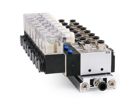
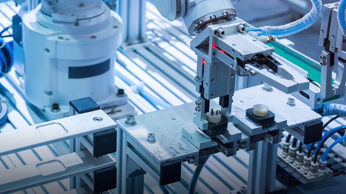
Valve manifolds control multiple pneumatic movements on automated production lines, including transfer mechanisms, positioning units, sorting systems, and assembly stations.
They are used to operate pneumatic clamps, tooling fixtures, machine components, and robotic end-effectors, helping simplify centralized control of repetitive operations.
In packaging equipment, manifolds control cylinders for feeding, gripping, folding, sealing, cutting, and product sorting. Their compact arrangement is useful where installation space is limited.
Automotive production lines use valve manifolds to control pneumatic fixtures, conveyor mechanisms, assembly tools, and auxiliary equipment. Centralized valve arrangements help organize pneumatic circuits across stations with multiple operating sequences.
By integrating air distribution, switching, and electrical connections, solenoid valve manifolds provide a practical foundation for multi-actuator pneumatic systems. Selecting the appropriate manifold requires considering valve functions, actuator requirements, supply flow, exhaust capacity, electrical interfaces, and the possibility of future expansion.
 Normally Open or Normally Closed? Angle Seat Valve Selection Guide
 Why CNC Coolant Systems Prefer VNC Valves? A Reliable Solution for Leak Prevention
 VNB Process Valves: An Efficient Solution for Multi-Purpose Fluid Control
 Valve Freezing Prevention Tips for Winter Maintenance
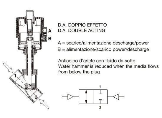 How to determine valve seat angle
You May Interest In

Dec 02, 2025 Blog
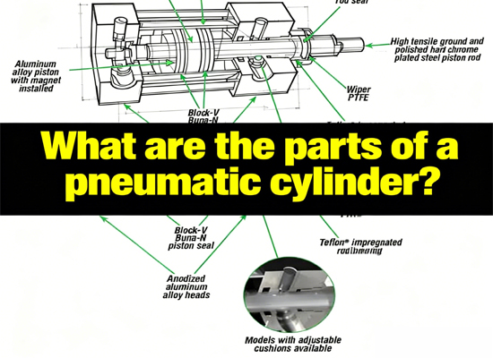
What are the parts of a pneumatic cylinder?

Apr 18, 2025 Blog
What is an Angle Seat Valve?
Get a free sample

Fokca is a brand of Ningbo Fokca Automation Co., Ltd.
Looking for custom pneumatic cylinder solutions? Visit our sister brand, Fescolo.→
© 2026 Ningbo Fokca Automation Co., Ltd. All rights reserved. Sitemap