Aug 25, 2026
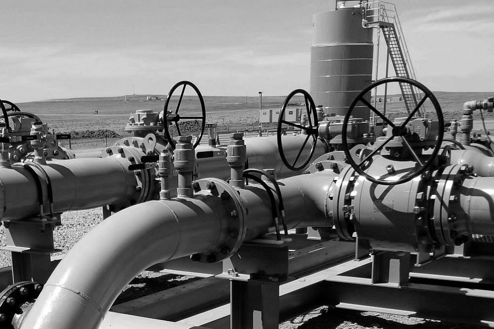
A pneumatic globe control valve regulates fluid flow by moving a valve plug linearly toward or away from a fixed seat. Unlike rotary valves, such as ball and butterfly valves, its internal throttling mechanism changes the flow passage through the relative position of the plug and seat. This arrangement makes it suitable for applications where stable flow regulation and controlled changes in process conditions are important.
The valve is operated by a pneumatic actuator, which converts compressed air pressure into linear mechanical movement. When combined with a valve positioner and an automatic control system, it can adjust the valve opening in response to changing process requirements.
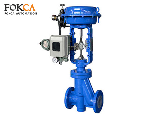
Pneumatic globe control valves are available in different configurations to accommodate varying pipeline sizes, pressure requirements, flow capacities, and installation conditions. Common product series include:
● GV100 Series Globe Control Valve
● GV200 Series Globe Control Valve
● GV300 Series Globe Control Valve
● GV400 Series Globe Control Valve
● GV500 Series Globe Control Valve
The specific construction and performance characteristics of each series should be evaluated against its product specifications and intended operating conditions.
A pneumatic globe control valve combines a fluid-control assembly with an actuator and, where required, a positioner. Each component contributes to the valve's ability to regulate flow and maintain reliable operation.
The valve body forms the main pressure-containing structure and provides the internal passage through which the medium flows. It houses the valve seat, plug, and other internal components while connecting the valve to the pipeline.
Material selection depends on the fluid, operating pressure, temperature, and potential corrosion or erosion. Common choices include cast steel, carbon steel, and stainless steel. For more demanding applications, special alloys may be considered according to the medium's compatibility requirements.
Globe valve bodies are commonly designed with straight-through flow passages. Angle-pattern and other configurations are also available for specific piping layouts and process requirements. The body design influences installation, flow resistance, and maintenance access.
The plug and seat form the primary throttling and shutoff assembly. The plug moves toward or away from the seat, changing the available flow area. Its profile influences the relationship between valve travel and flow rate.
Depending on the required control characteristics, plug designs may provide linear, equal-percentage, or other flow characteristics. The seat provides the sealing surface when the valve closes. Their materials and surface finishes must suit the operating medium, pressure, temperature, and expected wear conditions.
The valve stem connects the actuator to the plug and transmits linear movement. It must maintain suitable alignment and withstand the mechanical loads generated during operation.
Packing and stem seals help prevent fluid from escaping along the stem where it passes through the valve bonnet. Their material and construction should be selected according to the medium and operating temperature.
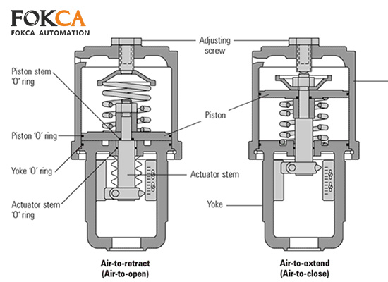
The actuator converts compressed air into the force needed to move the valve stem. Pneumatic globe control valves generally use linear-motion actuators, with piston and diaphragm designs being common options.
● Piston-type actuator
A piston actuator uses compressed air to move a piston inside a cylinder. The piston transfers force through a push rod to the valve stem. Depending on the design, it can be single-acting or double-acting.
A single-acting actuator uses compressed air for movement in one direction and a spring for the return stroke. A double-acting actuator uses air pressure to drive movement in both directions, making it suitable for applications requiring controlled force throughout the stroke.
● Diaphragm-type actuator
A diaphragm actuator uses air pressure acting on a flexible diaphragm to generate linear movement. A spring provides the opposing force and determines the actuator's return direction when air pressure is released.
Its relatively simple construction makes it a common option for control valves. The available thrust and stroke depend on the actuator's size, spring configuration, and operating pressure.
A valve positioner helps the actuator achieve the position requested by the control system. It receives a command signal, compares the requested position with actual valve travel, and adjusts the actuator's air pressure accordingly.
Depending on the system configuration, the input may be an electrical signal such as 4–20 mA or a pneumatic signal. By correcting positioning errors, the positioner can improve control accuracy and compensate for changes in friction or process forces.
The operating process involves three coordinated stages: receiving a control command, moving the actuator, and adjusting the flow passage.
● Opening: When the control system requests a larger flow rate, the positioner adjusts the actuator pressure to move the stem in the opening direction. The plug gradually separates from the seat, increasing the available flow area.
● Closing: When a smaller flow rate or shutoff is required, the positioner changes the actuator pressure to move the plug toward the seat. At the closed position, the plug contacts the seat to restrict or stop flow. Actual shutoff performance depends on the valve's sealing design and condition.
● Flow regulation: During normal control operation, the plug can remain at an intermediate position rather than moving fully open or closed. The positioner continuously adjusts actuator pressure to maintain the requested travel as operating conditions change.
It is important to distinguish valve position from actual flow rate. A valve opening of 50% does not necessarily produce 50% of its rated flow. The relationship depends on the plug's flow characteristic, pressure differential, medium properties, and pipeline conditions. Correct valve sizing is therefore essential for stable process control.
Pneumatic globe control valves offer several benefits in automated fluid systems:
● Adjustable flow control: The linear plug-and-seat arrangement supports controlled throttling when paired with a suitable positioner.
● Responsive operation: Pneumatic actuators can respond quickly to control commands, depending on actuator size, air supply, and control configuration.
● Reliable shutoff: The plug-and-seat assembly provides a defined closing interface, although the required leakage class must be specified.
● Industrial suitability: Appropriate body, trim, and seal materials allow these valves to operate in a range of industrial process environments.
● No electrical drive at the actuator: Pneumatic actuation avoids an electric motor at the valve itself. However, this alone does not establish explosion-proof certification for the complete installation.
There are also limitations to consider. Globe valves generally create more flow resistance than full-bore ball valves, particularly when the flow passage is restricted. Their body and actuator assemblies may also require more installation space. In addition, the actuator, positioner, packing, and internal sealing components need periodic inspection and maintenance.
Pneumatic globe control valves are used where automated adjustment of liquid or gas flow is required. Common applications include water treatment, chemical processing, power generation, heating and cooling systems, and industrial production lines.
In these systems, the valve can help regulate process flow and support temperature or pressure control loops. For example, a temperature controller may send a signal to the positioner, which adjusts the valve opening to change the flow of heating or cooling medium.
The suitability of a particular valve depends on the medium, pressure and temperature range, required flow capacity, control accuracy, and actuator configuration. Engineers should also consider the available compressed-air supply, installation space, maintenance access, and required failure position before selecting a model.
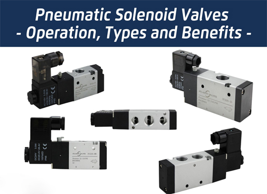 Pneumatic Solenoid Valves: Working Principles, Types and Applications
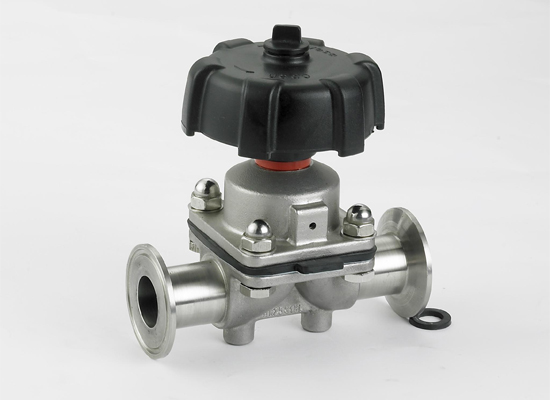 A Basic Guide to Diaphragm Valves: Features, Types and Applications
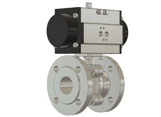 How Does a Pneumatic Ball Valve Operate? A Practical Guide
 Why Does Transparent PU Tubing Turn Yellow
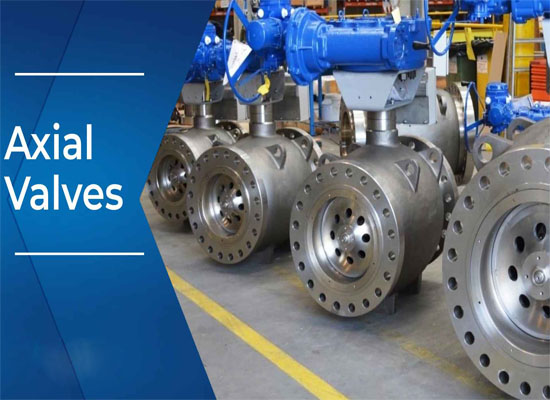 Comprehensive Analysis of Pneumatic Axial Flow Control Valves
You May Interest In

Dec 02, 2025 Blog
What are the parts of a pneumatic cylinder?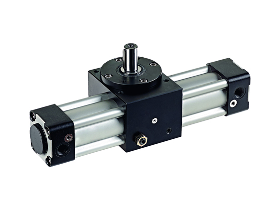


Apr 18, 2025 Blog
What is an Angle Seat Valve?
Get a free sample

Fokca is a brand of Ningbo Fokca Automation Co., Ltd.
Looking for custom pneumatic cylinder solutions? Visit our sister brand, Fescolo.→
© 2026 Ningbo Fokca Automation Co., Ltd. All rights reserved. Sitemap