Aug 18, 2026

In industrial fluid systems, maintaining a stable flow rate is essential for process efficiency, product quality, and equipment safety. A pneumatic globe control valve combines the throttling characteristics of a globe valve with the automated operation of a pneumatic actuator. It is commonly used to regulate the flow of liquids, gases, and steam in industrial processes.
Unlike an on-off valve, which mainly operates in fully open or fully closed positions, a pneumatic globe control valve can adjust its opening continuously to meet changing process requirements.
A pneumatic globe control valve consists of two main assemblies: the globe valve body and the pneumatic actuator. Additional components, such as a valve positioner, improve control accuracy.
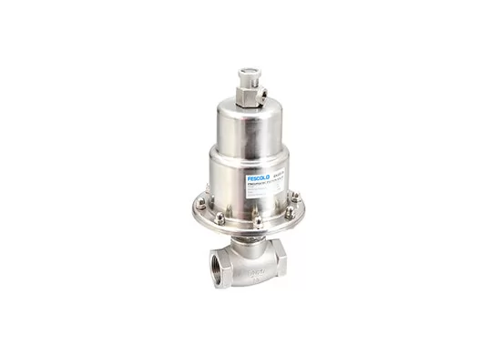
The valve body contains the flow passages, valve seat, plug, and other internal components. As the plug moves toward or away from the seat, the flow area changes, regulating the amount of fluid passing through the valve.
Common body materials include carbon steel, stainless steel, and other alloys. Material selection depends on the fluid medium, operating pressure, temperature, and corrosion requirements.
The pneumatic actuator converts compressed air pressure into mechanical movement. Depending on its design, it may use a diaphragm or piston to move the valve stem and adjust the plug position.
Actuators can be configured for air-to-open or air-to-close operation. Spring-return designs can also provide a predefined fail position when the air supply is lost, provided the actuator and valve are correctly configured.
A valve positioner compares the control signal with the actual valve position and adjusts the actuator's air pressure accordingly. This helps the valve follow the required opening more accurately, especially when process forces or friction affect movement.
A pneumatic globe control valve regulates flow by changing the position of its internal plug.
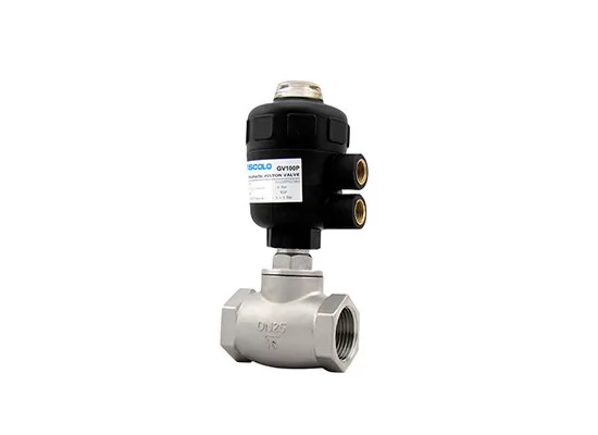
During operation, a controller sends a command to the valve positioner. The positioner adjusts the air pressure supplied to the actuator, causing the valve stem and plug to move. As the plug changes position, the opening between the plug and seat changes, increasing or reducing the flow rate.
A typical control sequence is:
① The process controller sends a control signal.
② The positioner converts the command into an appropriate pneumatic output.
③ The actuator moves the valve stem.
④ The plug adjusts the flow passage.
⑤ The positioner monitors valve position and corrects deviations.
Common control signals include 4–20 mA electrical signals and pneumatic signals such as 3–15 psi, depending on the control system and positioner configuration.
It is important to note that valve opening is not necessarily proportional to actual flow. Flow characteristics, pressure differential, fluid properties, and system conditions all influence the final flow rate.
Pneumatic globe control valves offer several benefits for industrial flow regulation.
| Advantages | Limitations |
| Accurate throttling with a suitable positioner | Requires a reliable compressed air supply |
| Fast response and automated operation | Air quality must be properly maintained |
| Suitable for continuous flow regulation | Larger models can be bulky and heavy |
| Available in different materials and configurations | Moving parts and seals require periodic maintenance |
| Pneumatic actuation is suitable for many industrial environments | Air consumption and operating costs depend on actuator design |
Another important consideration is pressure drop. Globe valves generally provide effective throttling, but their flow path can create a relatively high pressure loss compared with some other valve designs. Engineers should therefore consider flow capacity, pressure differential, and energy consumption when selecting a valve.
Pneumatic globe control valves are used in processes where fluid flow must be adjusted automatically.
● Chemical processing: Regulating chemical feed rates and process fluid flow.
● Water treatment: Controlling water and chemical dosing flows.
● Power generation: Adjusting water, steam, and other process flows within suitable pressure and temperature ratings.
● Oil and gas: Regulating process fluids in production and processing equipment.
The valve body, trim, seals, and actuator must be selected according to the actual medium and operating conditions. Applications involving corrosive chemicals, high temperatures, or high-pressure steam require particular attention to material compatibility and pressure-temperature ratings.
Choosing the right valve requires more than matching the pipeline connection size. Engineers should evaluate the required flow rate, inlet and outlet pressures, fluid temperature, medium properties, and control accuracy.
The valve's flow coefficient (Cv or Kv) is also important because it indicates its flow capacity under specified conditions. An incorrectly sized valve may cause excessive pressure loss, unstable control, or poor adjustment at low flow rates.
A properly selected pneumatic globe control valve, combined with a suitable actuator and positioner, can provide stable and repeatable flow regulation in automated industrial systems.
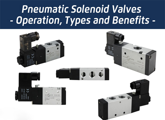 Pneumatic Solenoid Valves: Working Principles, Types and Applications
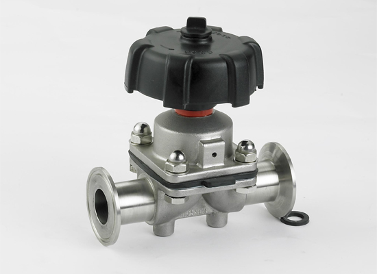 A Basic Guide to Diaphragm Valves: Features, Types and Applications
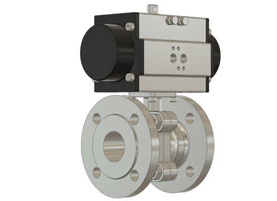 How Does a Pneumatic Ball Valve Operate? A Practical Guide
 Why Does Transparent PU Tubing Turn Yellow
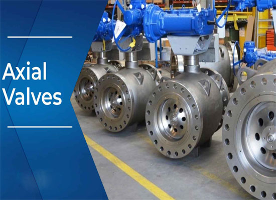 Comprehensive Analysis of Pneumatic Axial Flow Control Valves
You May Interest In


Dec 02, 2025 Blog
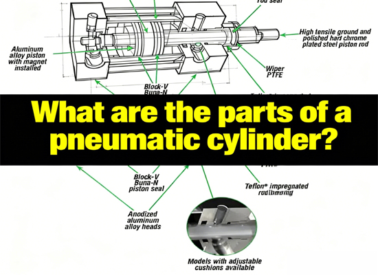
What are the parts of a pneumatic cylinder?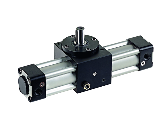




Apr 18, 2025 Blog
What is an Angle Seat Valve?
Get a free sample

Fokca is a brand of Ningbo Fokca Automation Co., Ltd.
Looking for custom pneumatic cylinder solutions? Visit our sister brand, Fescolo.→
© 2026 Ningbo Fokca Automation Co., Ltd. All rights reserved. Sitemap