Aug 24, 2026
In an automated fluid control system, sending a command to open or close a valve does not necessarily mean that the valve has reached the required position. An actuator may fail to move because of insufficient air pressure, electrical faults, mechanical obstruction, or other operating problems.
A valve limit switch helps solve this problem by providing electrical feedback about the valve's position. It allows a PLC or control system to verify whether the valve has reached a preset position, usually fully open or fully closed. This feedback improves process monitoring, supports automatic sequencing, and helps operators identify abnormal conditions.
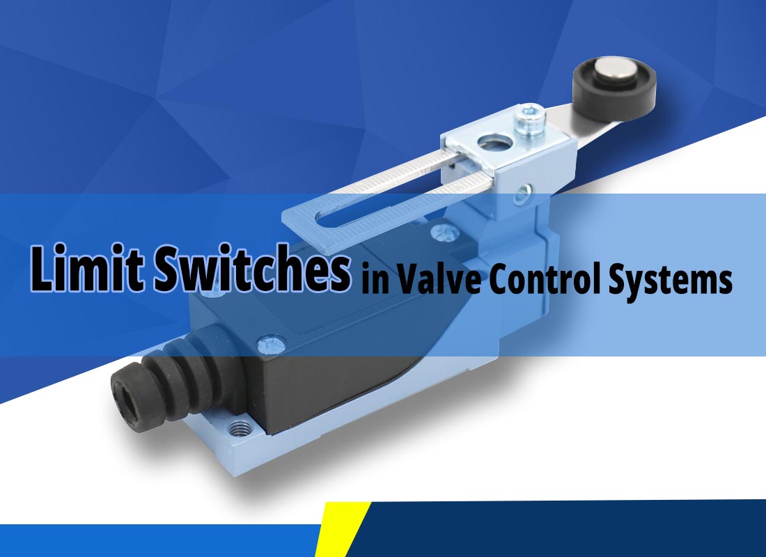
A valve limit switch is an electromechanical or electronic switching device used to detect and report a valve's position. It is commonly installed on top of a pneumatic actuator or connected to an electric actuator through a suitable mounting mechanism.
When the actuator moves the valve to a preset position, a mechanical cam or proximity target activates the switch. The device then sends an electrical signal to a PLC, control panel, or monitoring system.
For example, a pneumatic ball valve may have a limit switch box with two internal switches. One indicates the fully open position, while the other indicates the fully closed position. The control system uses these signals to confirm the valve's operating status.
It is important to distinguish between discrete limit switches and continuous position transmitters. Standard limit switches generally report specific positions rather than the exact percentage of valve opening. Continuous position feedback requires a suitable position sensor or transmitter.
Valve limit switches commonly operate through mechanical contact or non-contact sensing.
Mechanical limit switches use a physical contact mechanism. As the valve actuator rotates or moves linearly, a cam, lever, or other moving component presses the switch mechanism.
This changes the internal electrical contacts, generating a signal that indicates the valve has reached a preset position.
Mechanical switches are widely used because of their relatively simple construction and straightforward operation.
Proximity switches detect the position of a moving target without requiring direct mechanical contact. Depending on the design, they may use magnetic, inductive, or other sensing technologies.
For example, a magnetic sensor can detect a magnet attached to a moving actuator component. When the magnet reaches the sensing position, the switch changes its output state.
Proximity switches reduce mechanical contact and wear, making them suitable for applications requiring frequent operation.
Limit switches can also be classified according to their electrical contact configuration:
● Normally Open (NO): The electrical circuit is open in its normal, unactuated state. It closes when the switch is activated.
● Normally Closed (NC): The circuit is closed in its normal, unactuated state. It opens when the switch is activated.
Some limit switch devices provide both NO and NC contacts, allowing engineers to select the appropriate signal configuration for the control system.
The choice depends on the PLC input design, wiring arrangement, and required fault-detection logic. A normally closed contact alone does not guarantee a fail-safe system; the complete circuit and diagnostic strategy must be considered.
Pneumatic actuators are commonly used to operate ball valves, butterfly valves, and other automated valves. A limit switch box provides feedback on whether the actuator has reached its open or closed position.
On an automated production line, for example, the PLC may command a valve to open and wait for the open-position signal before starting the next operation. If the signal does not arrive within the expected time, the system can generate an alarm or stop the sequence.
This helps prevent process errors caused by incomplete valve movement.
Chemical plants often use automated valves to control the flow of process media under demanding pressure and temperature conditions.
Limit switches installed on suitable valve actuators can provide remote confirmation of valve position. Their signals may also be incorporated into process interlocks.
For example, a transfer pump may only be permitted to start after the required pipeline valve has been confirmed open. If the expected position signal is missing, the control system can prevent the next operation.
The limit switch itself does not prevent leakage or guarantee safe operation. Its effectiveness depends on correct installation, suitable component selection, and properly designed control logic.
In water treatment plants and distribution networks, limit switches help monitor automated isolation and switching valves.
Position feedback allows operators to check whether a valve has reached its commanded end position. The information can be transmitted to a central monitoring system for remote supervision and alarm management.
However, a conventional open/closed limit switch cannot measure intermediate valve opening accurately. Applications requiring continuous flow or valve-position regulation need an appropriate modulating actuator and position feedback device.
In industrial automation, position switches can form part of a safety or interlock arrangement. They help confirm that equipment has reached a required position before another operation is permitted.
Common configurations include:
● Open-position and closed-position switches: Provide separate signals for the two end positions.
● Position monitoring switches: Report whether an actuator has reached a specified mechanical position.
● Explosion-protected switch assemblies: Designed and certified for installation in specified hazardous areas.
● Weather-resistant switch enclosures: Provide protection against environmental exposure according to their rated IP classification.
Not every limit switch is a safety-rated device. Where a valve position signal is used in a safety instrumented function, the switch, wiring, control system, and complete safety loop must meet the applicable safety requirements. Explosion protection and ingress protection are also different characteristics and should be evaluated separately.
A faulty limit switch can send incorrect feedback or fail to report a valve's actual position. Common symptoms include:
● The PLC does not receive an open or closed signal even though the valve has moved.
● The control system indicates that the valve is open when it is actually closed.
● The valve completes its movement, but the next automated operation does not start.
● Position signals fluctuate or appear intermittently.
● The system generates repeated alarms or stops unexpectedly.
Possible causes include damaged contacts, loose wiring, incorrect cam adjustment, sensor misalignment, moisture ingress, or a failed proximity sensor.
When troubleshooting, first compare the physical valve position with the control system indication. Then inspect the switch mechanism, wiring, power supply, sensor alignment, and PLC input. Do not assume that a missing feedback signal means the valve actuator itself has failed.
No. A limit switch and a relay perform different functions in an electrical control system.
| Feature | Limit Switch | Relay |
| Main function | Detects position or mechanical movement | Controls electrical circuits |
| Operating principle | Mechanical contact or proximity sensing | Electromagnetic or electronic switching |
| Trigger | Physical movement or detected target | Electrical control signal |
| Common applications | Valve position feedback, stroke detection | Motor control, signal switching, electrical interlocking |
| Typical role | Sends a position signal | Switches one or more electrical circuits |
A limit switch may provide an input signal to a PLC or relay circuit. The relay can then control another electrical device according to the system's logic. They often work together but are not interchangeable.
When selecting a limit switch for a valve actuator, consider the following factors:
● Switch type: Choose mechanical or proximity sensing according to operating frequency and installation requirements.
● Contact configuration: Confirm NO, NC, or combined contact availability and compatibility with the PLC input.
● Electrical ratings: Check the rated voltage, current, and output type.
● Enclosure protection: Select an appropriate IP rating for dust, moisture, and outdoor exposure.
● Hazardous-area requirements: Verify the relevant explosion-protection certification when installation conditions require it.
● Mechanical compatibility: Confirm actuator mounting dimensions, shaft interface, and switching travel.
A correctly selected limit switch provides reliable valve position feedback and helps the control system respond appropriately when actual valve movement differs from the command.
 Pneumatic Solenoid Valves: Working Principles, Types and Applications
 A Basic Guide to Diaphragm Valves: Features, Types and Applications
 How Does a Pneumatic Ball Valve Operate? A Practical Guide
 Why Does Transparent PU Tubing Turn Yellow
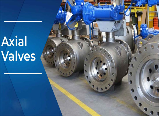 Comprehensive Analysis of Pneumatic Axial Flow Control Valves
You May Interest In


Dec 02, 2025 Blog
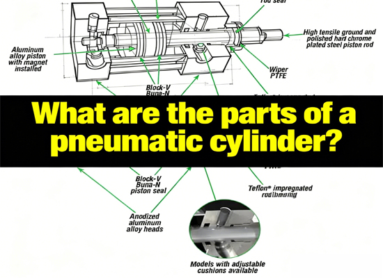
What are the parts of a pneumatic cylinder?





Apr 18, 2025 Blog
What is an Angle Seat Valve?
Get a free sample

Fokca is a brand of Ningbo Fokca Automation Co., Ltd.
Looking for custom pneumatic cylinder solutions? Visit our sister brand, Fescolo.→
© 2026 Ningbo Fokca Automation Co., Ltd. All rights reserved. Sitemap