Aug 27, 2026
Industrial dust collection systems must maintain sufficient airflow while preventing dust from accumulating on filter bags and cartridges. As filtration continues, particles gradually build up on the filter surface, increasing pressure drop and reducing system performance. Pulse-jet cleaning addresses this problem by releasing short bursts of compressed air to remove accumulated dust.
A pilot-operated pulse solenoid valve controls these bursts. By combining electromagnetic pilot control with diaphragm operation, it can release a large volume of compressed air through a relatively small electrical control mechanism. Its performance directly affects cleaning effectiveness, compressed-air consumption, and the stability of the dust collection system.
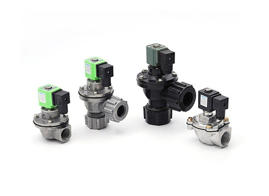
A pilot-operated pulse solenoid valve is a specialized pneumatic valve commonly used in industrial pulse-jet dust collectors. It uses an electromagnetic pilot mechanism to control the movement of a main diaphragm, allowing compressed air stored in an air reservoir to discharge rapidly into the cleaning pipe.
Unlike a conventional direct-acting valve, the solenoid coil does not need to move the main diaphragm directly. Instead, it controls a smaller pilot passage. The resulting pressure difference drives the main valve open.
This arrangement allows the valve to handle relatively high airflow while keeping the electrical control mechanism compact.
The construction of a pilot-operated pulse valve varies by manufacturer, but common components include:
● Solenoid coil: Generates electromagnetic force when energized.
● Pilot valve: Controls pressure in the diaphragm's control chamber.
● Diaphragm assembly: Acts as the main sealing and moving element, opening and closing the compressed-air passage.
● Valve body: Contains the main air passage and internal chambers.
● Spring and seals: Help restore the diaphragm and maintain reliable sealing.
● Electrical connector: Connects the coil to the pulse controller.
The diaphragm is particularly important because it experiences repeated pressure changes and mechanical movement. Its material must be suitable for the operating temperature, compressed-air quality, and expected switching frequency.
The operating process relies on pressure differences across the diaphragm.
Standby condition: Compressed air enters the valve. Pressure builds in the diaphragm's upper control chamber through a small equalizing passage. The diaphragm remains seated, preventing the main airflow passage from opening.
Electrical activation: The pulse controller briefly energizes the solenoid coil. The electromagnetic force moves the pilot plunger, opening the pilot exhaust passage.
Main valve opening: Air escapes from the upper control chamber, reducing pressure above the diaphragm. The higher pressure beneath the diaphragm then lifts it, allowing compressed air from the reservoir to enter the blow pipe.
Pulse discharge: A strong, short airflow burst travels through the blow pipe and nozzles into the filter bags or cartridges. The resulting pressure wave and reverse airflow help dislodge dust from the filter surface.
Valve reset: When the electrical signal ends, the pilot passage closes. Air refills the control chamber through the equalizing passage, allowing pressure to recover. The diaphragm returns to its seat and stops the main airflow.
This sequence repeats according to the cleaning controller's programmed settings.
These valves are mainly associated with industrial dust collection and filtration equipment.
Baghouse dust collectors: Pulse cleaning removes accumulated dust from filter bags, helping maintain airflow and filtration performance in cement plants, metal processing facilities, and other industrial environments.
Cartridge dust collectors: Used in compact filtration equipment, including systems handling welding fumes, laser cutting smoke, and fine industrial dust.
Pneumatic dust removal systems: Suitable for cleaning filter surfaces and certain dust-handling equipment where a controlled compressed-air burst is required.
Industrial exhaust treatment: Used in filtration stages of systems handling dust from boilers, material processing, and manufacturing operations. Their effectiveness depends on the filter design and the characteristics of the collected particles.
Selecting a suitable pulse valve is only part of achieving effective dust removal. The compressed-air supply, cleaning sequence, and filter arrangement must work together.
Pulse width determines how long the valve remains activated, while the interval determines how frequently cleaning occurs. Excessively short pulses may not deliver enough cleaning energy. Unnecessarily long or frequent pulses can waste compressed air and increase diaphragm wear.
The appropriate settings depend on filter media, dust characteristics, valve capacity, and system pressure. Differential-pressure control can help trigger cleaning according to actual filter resistance rather than relying entirely on fixed intervals.
Valve port size, diaphragm design, reservoir volume, blow-pipe dimensions, and nozzle arrangement all influence the cleaning airflow. An undersized valve may not deliver sufficient air, while an oversized valve can increase air consumption without necessarily improving cleaning results.
The system should also maintain stable compressed-air pressure. Some dust collectors operate around 0.4–0.6 MPa, but the correct range must be confirmed against the valve specifications and equipment design.
Dividing a dust collector into cleaning zones helps prevent excessive simultaneous air demand. Activating valves in sequence allows the reservoir pressure to recover between pulses and supports more consistent cleaning across the filter elements.
The blow pipe should be positioned and aligned according to the filter manufacturer's recommendations. Incorrect nozzle positioning can create uneven airflow distribution, reducing cleaning effectiveness and increasing compressed-air consumption.
Before installation, confirm that the coil voltage and electrical connection match the controller. Check the thread standard, connection dimensions, pressure rating, and air inlet arrangement. Use compatible thread sealants where required, and avoid excessive tightening that could damage the valve body.
The compressed-air supply should be clean and sufficiently dry to reduce contamination and internal corrosion. After installation, check for air leakage and confirm that each valve responds correctly to the controller.
Regular maintenance should focus on:
● Inspecting diaphragms for cracks, deformation, and wear.
● Checking pilot passages for blockage or contamination.
● Examining seals and electrical connections.
● Monitoring abnormal leakage, delayed switching, or weak cleaning pulses.
● Confirming that reservoir pressure remains stable during operation.
If a valve fails to produce a strong pulse, possible causes include insufficient supply pressure, blocked pilot passages, diaphragm damage, electrical faults, or an incorrectly configured controller. Replacing the valve without identifying the cause may not solve the problem.
A suitable valve should match the dust collector's air reservoir, blow-pipe arrangement, operating pressure, pulse frequency, and installation environment. Buyers should also verify coil voltage, port size, connection standard, diaphragm material, temperature range, and available replacement parts.
Pilot-operated pulse solenoid valves support efficient filter cleaning by combining electrical control with high-volume compressed-air discharge. Their actual performance, however, depends on the complete filtration system. Correct sizing, stable air supply, appropriate pulse settings, and routine diaphragm maintenance are essential for reliable long-term operation.
 Mastering Precision: Why Air Pressure Regulators Are Essential in Pneumatic Systems
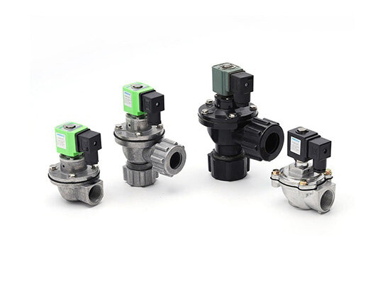 How Pilot-Operated Pulse Solenoid Valves Improve Dust Collection Efficiency
 Angle Seat Valve vs Ball Valve: Which Is Better for Automated Production Lines?
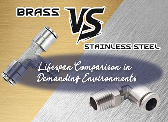 Brass vs Stainless Steel Pneumatic Fittings: Which Lasts Longer
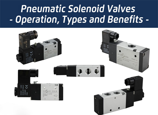 Pneumatic Solenoid Valves: Working Principles, Types and Applications
You May Interest In

Dec 02, 2025 Blog
What are the parts of a pneumatic cylinder?
Apr 18, 2025 Blog
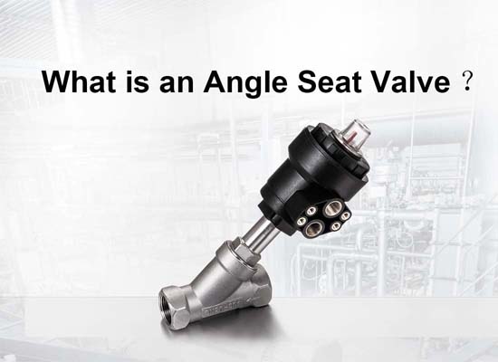
What is an Angle Seat Valve?
Get a free sample

Fokca is a brand of Ningbo Fokca Automation Co., Ltd.
Looking for custom pneumatic cylinder solutions? Visit our sister brand, Fescolo.→
© 2026 Ningbo Fokca Automation Co., Ltd. All rights reserved. Sitemap




 None