Mar 17, 2026

In industrial fluid control systems, valve sizing directly affects system stability and energy efficiency. For commonly used angle seat valves, especially pneumatic angle seat valves, engineers rely heavily on one key parameter: the Cv value.
The Cv value, or flow coefficient, represents the flow capacity of a valve under a specific pressure difference. It serves as a critical link between pipeline design and valve performance.
When valve sizing is incorrect, even a high-quality valve may cause unstable control, excessive pressure loss, or increased energy consumption. For distributors, equipment manufacturers, and plant engineers, understanding how Cv values influence angle seat valve selection is essential.
The Cv value is defined as the flow rate of water in gallons per minute that passes through a valve with a pressure drop of 1 psi.
For a typical angle seat piston valve or 2 2 way angle seat valve, the Cv value mainly depends on valve size, internal flow path design, and seat structure.
Modern angled seat valve designs often feature streamlined flow channels that minimize turbulence and pressure drop. Because of this design, angle seat valves are widely used in steam systems, beverage processing equipment, and industrial automation lines.
From a system design perspective, the correct Cv value must match the pipeline flow rate and pressure conditions.
Engineers typically estimate Cv using a simplified flow equation:
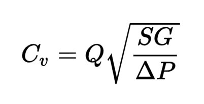
◆ Q = Flow rate (GPM)
◆ SG = Specific gravity of the fluid
◆ ΔP = Pressure drop across the valve (psi)
Although calculations differ slightly for steam or compressed air systems, the basic concept remains the same: determine the valve capacity required to pass the desired flow under given pressure conditions.
The table below shows typical Cv ranges for different sizes of pneumatic angle seat valves.
| Valve Size | Typical Cv Value | Typical Flow Capacity | Common Application |
|---|---|---|---|
| DN15 (1/2") | 4 – 6 | Small flow pipelines | Laboratory systems |
| DN20 (3/4") | 7 – 10 | Medium flow control | Food processing |
| DN25 (1") | 12 – 16 | Steam or compressed air | Industrial automation |
| DN40 (1 1/2") | 25 – 35 | Large flow pipelines | Chemical equipment |
These values are typically provided in manufacturer catalogs or angle seat valve diagrams.
In some projects, engineers intentionally select larger valves to provide a safety margin. However, an oversized pneumatic angle seat valve can reduce control accuracy.
When the valve operates at very small openings, minor actuator movements may cause large changes in flow rate. This makes the system difficult to regulate precisely.
Larger valves also require bigger actuators, which may increase compressed air consumption and equipment costs in automated systems.
If the Cv value is too small, fluid must pass through the valve at higher velocity, resulting in significant pressure drop.
In steam pipelines or high-flow liquid systems, excessive pressure loss can reduce system efficiency and force pumps or compressors to operate at higher power levels.
Additionally, higher flow velocity may accelerate wear inside the valve body, shortening the service life of the angle seat valve.
In most engineering designs, valves perform best when operating at 40–80% opening, which balances control precision and energy efficiency.
Experienced system designers usually combine theoretical calculations with practical knowledge when selecting angle seat valves:
◆ Calculate the required Cv value based on flow and pressure conditions
◆ Ensure the valve operates within a moderate opening range
◆ Avoid selecting excessively large valves
◆ Refer to manufacturer data and angle seat valve working principle documentation
Proper valve sizing ensures stable flow control while reducing long-term operating costs in industrial systems.
(FK9025)
 Valve Starting Pressure: Why Minimum Pressure Matters in Valve Operation
 Pneumatic Quick Coupling for High-Cycle Use: Why Wear Resistance Matters
 Angle Seat Valve Packing Seal Structure and Leakage Control in Industrial Applications
 Cv Value Selection: Sizing Principles for Angle Seat Valves in Flow Control Systems
 Why Industrial Production Lines Increasingly Use Pneumatic Quick Coupling
You May Interest In


Nov 13, 2025 Blog
How to check valve seat angle?
Apr 18, 2025 Blog
What is an Angle Seat Valve?


Mar 06, 2026 Blog
IP Protection Rating of Solenoid Valve Coils


Get a free sample

FOKCA ©1998-2026 All Rights Reserved Sitemap