Feb 17, 2026

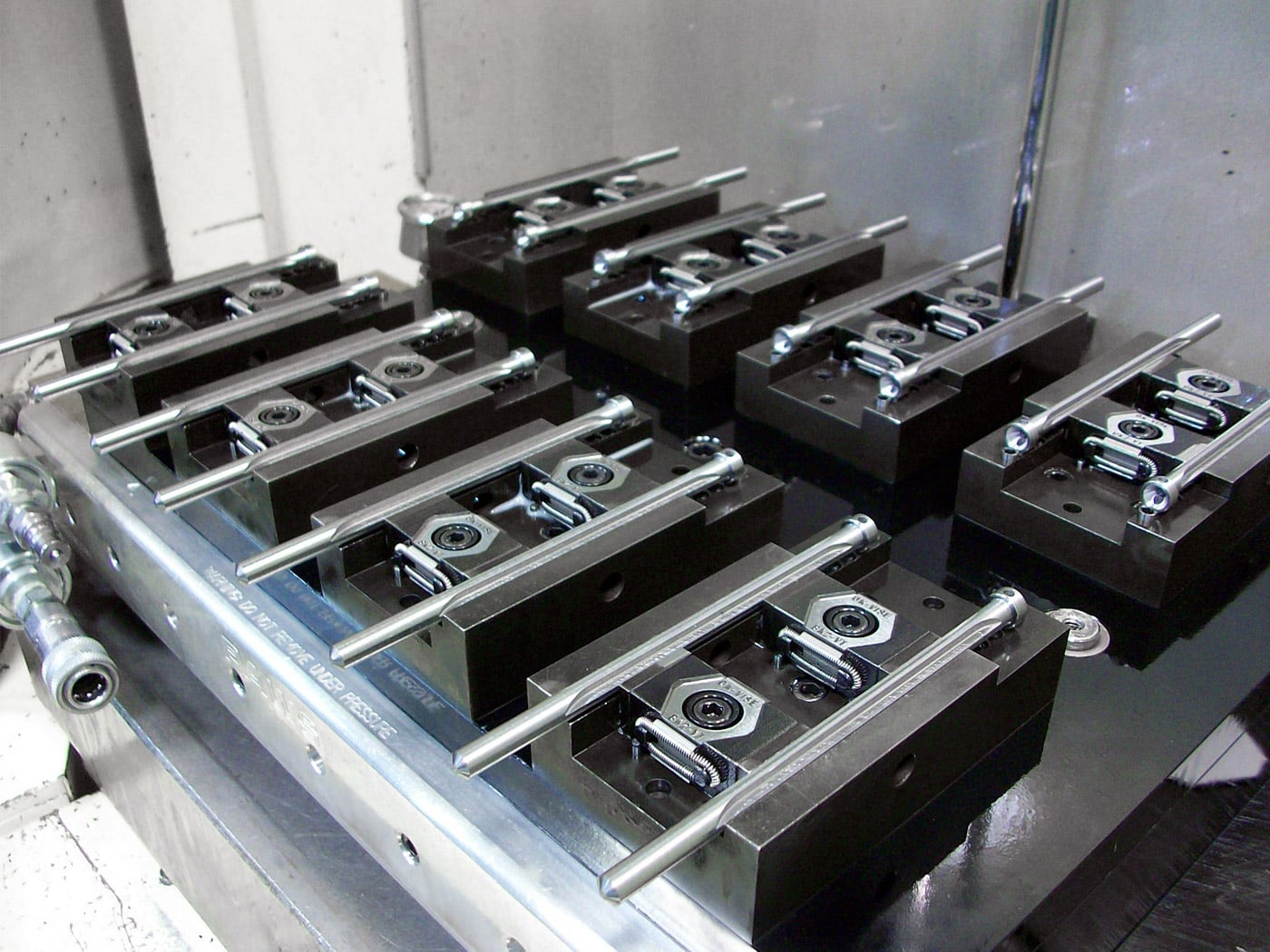
In automated production lines, pneumatic fixtures are often required to keep their state after power loss to prevent workpiece falling or mechanism disorder. The 3 way solenoid valve plays the central role in this logic. By switching the connection between supply and exhaust ports, the valve enables the fixture to remain clamped or to release when de-energized. This is not only an electrical issue but a combination of air circuit design and valve function. Understanding the relation between port configuration and actuator behavior is essential for equipment engineers.
Most fixtures are driven by single-acting or double-acting cylinders. A 3/2 way solenoid valve integrates supply and exhaust functions in one body, making the circuit compact. Compared with 2-way valves, the 3-way pneumatic solenoid valve can redirect air instantly and bring the actuator to a predefined safe position.
Two safety strategies are common:
◆ Power-off clamp to secure the part
◆ Power-off release to avoid mechanical damage
These are achieved through 3 way normally closed solenoid valve or 3 way normally open solenoid valve configurations.
A typical valve has P, A and R ports. The spool of a 3 way direct acting solenoid valve changes the connection when energized, while larger systems often adopt 3 way pilot operated solenoid valve.
| Power State | Port Connection | Cylinder Behavior | Fixture Result |
|---|---|---|---|
| Energized | P → A | Pressurized | Clamp/Release |
| De-energized | A → R | Exhausted | Hold/Release |
This structure makes solenoid valve 3 way control the most practical choice.
With a normally closed design, A connects to R after power loss. If the fixture uses spring force for clamping, the result is power-off clamp; if clamping depends on air pressure, it becomes power-off release. Therefore the mechanical design must match the valve logic.
Multi-station fixtures often use compact 3 way solenoid valve mounted on a manifold. The exhaust capacity of the exhaust port valve 3 way directly affects response time.
For single-acting cylinders, the 3 way valve for pneumatic cylinder is almost the only solution. Even for double-acting types, a 3-way scheme offers more predictable behavior in safety circuits.
High-load fixtures benefit from fast response 3 way solenoid valve. Coil selection of AC/DC 3 way solenoid valve must consider continuous duty and temperature rise.
Problems usually come from piping rather than the valve itself. Long exhaust tubing creates back pressure and slows reset. Correct layout following pneumatic directional control valve principles is crucial. In critical equipment, combining energy storage with industrial automation solenoid valves improves reliability.
(FK9025)
 Valve Starting Pressure: Why Minimum Pressure Matters in Valve Operation
 Pneumatic Quick Coupling for High-Cycle Use: Why Wear Resistance Matters
 Angle Seat Valve Packing Seal Structure and Leakage Control in Industrial Applications
 Cv Value Selection: Sizing Principles for Angle Seat Valves in Flow Control Systems
 Why Industrial Production Lines Increasingly Use Pneumatic Quick Coupling
You May Interest In


Dec 06, 2025 Blog
How to check pneumatic solenoid valve?

Dec 04, 2025 Blog
How does a single solenoid valve work?
Dec 03, 2025 Blog
What is double acting solenoid valve?
Dec 02, 2025 Blog
How to clean a pneumatic solenoid valve?
Dec 01, 2025 Blog
How to Wire and Install a Pneumatic Solenoid Valve?
Nov 30, 2025 Blog
How to select pneumatic solenoid valve?
Nov 29, 2025 Blog
Operational Mechanism of Pneumatic Solenoid Valves

Nov 27, 2025 Blog
What is pilot operated solenoid valve?


Get a free sample

Links: www.fescolo.com(Pneumatic)
FOKCA ©1998-2025 All Rights Reserved Sitemap