Nov 21, 2025
A pneumatic cylinder is an actuator that uses compressed air to generate linear or rotary motion. It is one of the most essential power components in any pneumatic system.
By converting air pressure into mechanical energy, cylinders drive machine mechanisms to perform pushing, pulling, clamping, lifting, positioning, and various handling operations, making them widely used in modern industrial automation. Depending on their structure and operating method, cylinders can be classified as single-acting, double-acting, rodless, rotary, and several other types. Each type operates differently and offers distinct motion characteristics and application scenarios.
Understanding how air cylinders work not only helps engineers make proper selection and design decisions but also supports diagnosing abnormal movements, improving system stability, and optimizing equipment maintenance and energy efficiency. Whether used in the pushing mechanism of packaging lines, the gripper actuation of robotic arms, positioning units in electronic assembly machines, or lifting modules in material-handling systems, cylinders play an indispensable role.
This article will take you through a clear and practical explanation of how different types of pneumatic cylinders operate, providing a solid foundation for better decision-making in selection, installation, troubleshooting, and system optimization.
A pneumatic cylinder is a commonly used simple actuator in industrial manufacturing. What are the functions of a pneumatic cylinder? Here are several points listed.
Energy Conversion
The basic function of a pneumatic cylinder is to convert the energy of compressed air into linear reciprocating mechanical motion, providing driving force for pneumatic systems.
Stable Force Output
By adjusting working pressure and cylinder bore, pneumatic cylinders can deliver stable and controllable pushing and pulling forces, meeting the requirements of various industrial applications.
Automation Capability
Pneumatic cylinders perform repetitive linear motions in automated equipment, such as pushing, clamping, positioning, and sorting operations.
Controllable Operation
When combined with solenoid valves, flow control valves, and sensors, pneumatic cylinders offer speed control, stroke control, and sequence control functionalities.
Long Service Life
With a simple structure and high reliability, pneumatic cylinders can operate stably over long periods in demanding industrial environments, including high-frequency, high-humidity, and dusty conditions.
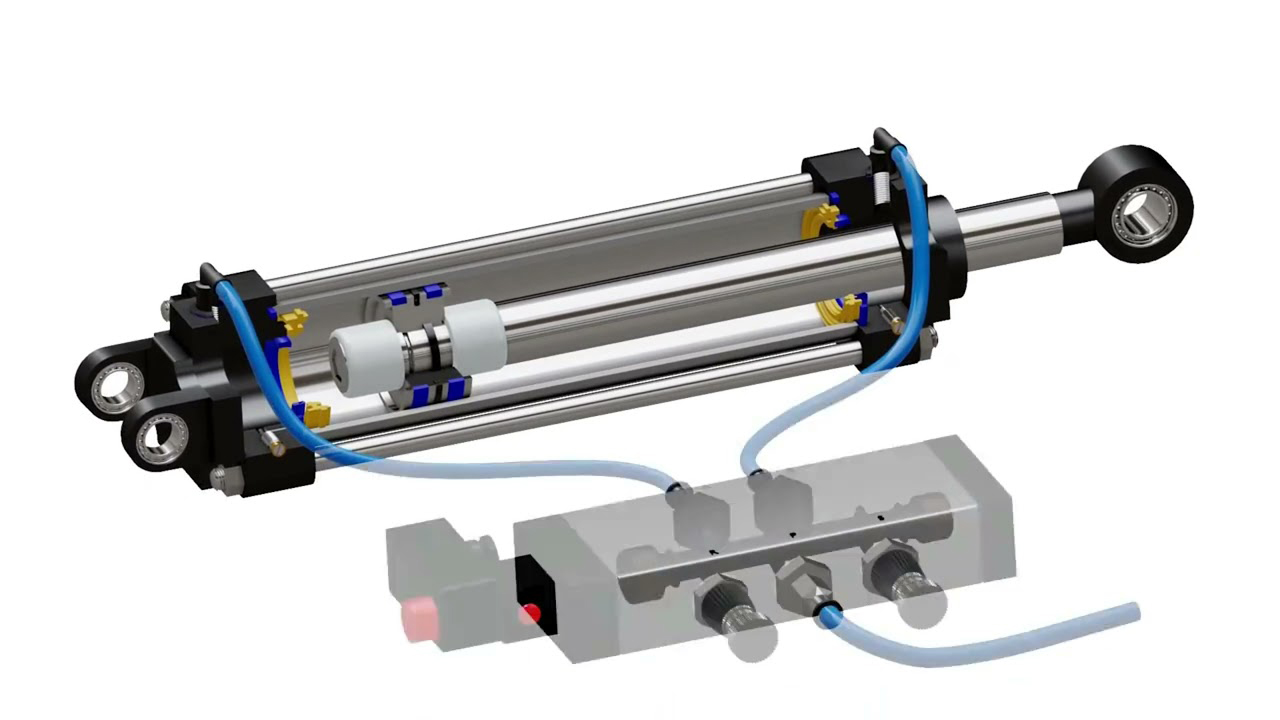
The normal operation of a cylinder requires cylinder components, mounting components, and other functional components.Cylinder components include the cylinder tube, piston, piston rod, seals, and cushioning devices.
| Component | Brief Description |
|---|---|
| Cylinder block | Main body that houses the piston and forms a sealed chamber |
| Piston | Moves inside the cylinder to generate linear motion |
| Piston rod | Transmits piston motion to the external load |
| End covers | Seal both ends of the cylinder block |
| Seals | Prevent air leakage inside the cylinder |
| Air inlet | Port for compressed air entry |
| Exhaust ports | Openings for air discharge during operation |
Mounting components include mounting accessories, mounting brackets, and cylinder hinges.Other functional components include guide bushings or guide sliders, magnetic sensors, quick exhaust valves, and speed control valves.Among them, components such as mounting brackets and sealing elements are available in various types. You can learn more through this article.
The basic working principle of a pneumatic cylinder is that compressed air enters the cylinder chamber and creates a pressure difference, which pushes the piston to move, thereby generating linear displacement or force output.

This type of cylinder has only one air port. Air pressure drives the piston in one direction, while the return stroke relies on an internal spring.
Features: Simple structure, low cost, suitable for short strokes or applications requiring motion in a single direction.
Applications: Automatic feeding push rods, clamping devices, light-duty return mechanisms.
This is the most common type of cylinder. Both ends of the cylinder have air ports, and the piston’s extension and retraction are controlled by air pressure. By switching a solenoid valve or manual valve, the airflow direction can be controlled to achieve reciprocating motion.
Features: Can output force in both directions, stroke is controllable, suitable for repetitive push-pull operations.
Applications: Robotic arm extension/retraction, automated assembly line push-pull operations, clamping or lifting devices.
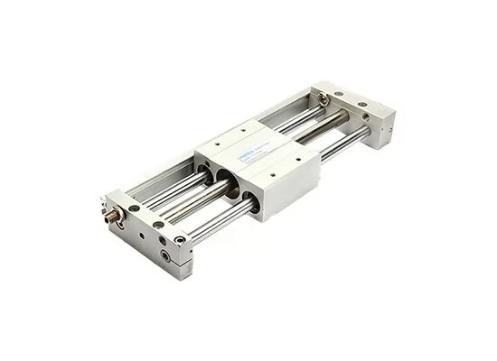
This cylinder has no external piston rod. The internal piston drives an external carriage via magnetic coupling or mechanical linkage, and the carriage moves along an external rail, achieving linear motion.
Features: Saves installation space, allows long strokes, no exposed piston rod, suitable for long-stroke transport.
Applications: Automated conveying, assembly machinery, workpiece handling.
A guided cylinder adds guide rods or bushings at the cylinder ends or piston rod to enhance resistance to torque and side loads during piston movement.
Features: Improves precision and stability, capable of handling certain side loads.
Applications: Precision assembly, clamping fixtures, stamping assistance mechanisms.
The rotary cylinder works by using air pressure to drive an internal piston or gear mechanism, converting linear reciprocating motion into rotary motion, outputting angular displacement or torque.
Features: Enables rotational movement, commonly used in grippers or sorting devices.
Applications: Rotating grippers, robotic arm rotation, rotary sorting mechanisms.
Cylinder performance and efficiency during operation are influenced by key factors such as inlet/outlet control, speed control, position control, and output force. These factors determine the cylinder's motion direction, speed, precision, load capacity, and safety, and must be carefully considered during the design, installation, and operation of the cylinder.
Solenoid valves / Manual valves – Mainly used to control the extension and retraction of the cylinder, ensuring that the cylinder operates in the desired direction.
Throttle valves / Speed control valves – Used to make the cylinder move more smoothly, prevent impact or excessively fast motion, and improve operational precision and safety.
Mechanical limits / Magnetic sensors – Prevent the cylinder from exceeding its stroke, provide accurate position feedback, and enable automated control while protecting the machinery.
Cylinder force calculation – Ensures the cylinder can handle the load and complete the task, while matching the air supply pressure appropriately.
Fokca is a professional manufacturer specializing in the research, development, manufacturing, and sales of pneumatic cylinders and pneumatic components, with its own cylinder brand Fescolo Cylinder. Its product range covers standard cylinders, compact cylinders, rodless cylinders, guided cylinders, as well as various customized non-standard cylinders, which are widely used in industrial automation, machinery manufacturing, packaging, and logistics industries. If you need,just contact us directly!
The company is equipped with advanced CNC machining equipment and complete production lines, enabling in-house manufacturing of key components and comprehensive quality control to ensure product performance and stability. Supported by an experienced R&D team and flexible customization capabilities, Fokca is able to provide highly reliable pneumatic cylinder solutions with fast delivery to meet diverse operating conditions and application requirements.
You May Interest In

Dec 04, 2025 Blog
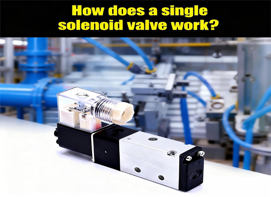
How does a single solenoid valve work?

Nov 07, 2025 Blog
How does a rodless pneumatic cylinder work?Links: www.fescolo.com(Pneumatic)
FOKCA ©1998-2025 All Rights Reserved Sitemap