What Is a Hydraulic System? How It Works and Why It Matters
A hydraulic system is a power transmission and control system that uses Hydraulic Oil as the working medium. By connecting five basic hydraulic components, it transmits energy and controls motion through the pressure of the liquid which typically include water, hydraulic oil, and emulsions.
The fundamental working principle behind hydraulic system is based on the physical property that hydraulic oil incompressible and capable of transmitting pressure. The system uses incompressible hydraulic oil to transmit pressure from one part of the system to another, enabling precise and powerful motion control.
Hydraulic System Components
A hydraulic system is a power transmission and control system that uses Hydraulic oil, most commonly petroleum-based.A hydraulic system has five fundamental components, including the hydraulic pump, hydraulic cylinder (or actuator), various hydraulic valves, as well as auxiliary elements such as the reservoir and filters.According to Pascal's principle: hydraulic fluid traveling through pipelines must be pressurized to transmit force efficiently and By increasing the force bearing area, it is possible to lift heavy objects with small force.
Which component creates hydraulic pressure?
The hydraulic pump is not only the component responsible for pressurizing the fluid but also serves as the most fundamental part of the entire hydraulic system.
Since the pressurized fluid acts as the medium for converting between mechanical energy and hydraulic energy, the hydraulic pump functions as the primary power source that enables this energy transformation by increasing the fluid's pressure.
Two Main Types of Hydraulic Pumps
In a hydraulic system, the pump serves as the primary power source, supplying the energy needed to pressurize the fluid and drive the system. There are three common types of hydraulic pumps, each with distinct characteristics, advantages, and drawbacks:
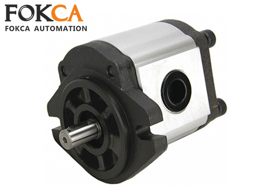
Gear Pump
Structure: Consists of two meshing gears—one driven by a motor, the other idler. As the gears rotate, sealed chambers are formed between the gear teeth, drawing in fluid at the inlet and pushing it toward the outlet.
Advantages:
Simple design
Low manufacturing cost
Compact size and lightweight
Suitable for low to medium pressure applications
Disadvantages:
Lower pressure and efficiency compared to vane and piston pumps
Higher pulsation and noise levels
Piston Pump
Structure: Uses multiple pistons that move back and forth inside cylinders. The pistons' reciprocating motion changes the chamber volume, allowing the pump to draw in fluid and discharge it under high pressure.
Advantages:
Capable of withstanding very high pressures
High efficiency and long service life
Excellent for high-precision and high-load applications
Disadvantages:
Complex design and higher manufacturing cost
Demands more maintenance and cleaner operating conditions
Typical Applications:
Aerospace systems, high-pressure industrial equipment, and precision hydraulic machinery
The hydraulic pump is responsible for providing energy and power in a hydraulic system, acting as the driving force behind fluid movement.
In addition, hydraulic valves play a vital role in controlling the behavior of the pressurized fluid.
Two Main Types of Hydraulic Valves
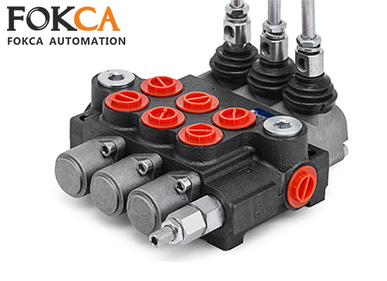
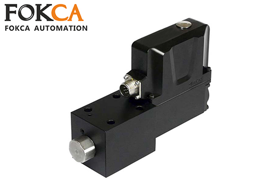
Hydraulic valves are regulating components of hydraulic systems. They regulate the direction, pressure, and flow rate of hydraulic fluid to ensure safe, efficient, and precise operation. The three main types of hydraulic valves are:
Directional Control Valve
Function: Controls the direction of hydraulic fluid flow, thereby determining whether an actuator (such as a cylinder) moves forward, backward, or stops.
Common Configurations:
2-way, 2-position (2/2) valve
4-way, 3-position (4/3) valve
Application: Used to switch fluid paths in circuits and activate or deactivate hydraulic functions.
Flow Control Valve
Function: Regulates the flow rate of hydraulic fluid to control the speed of actuators.
Working Principle: Adjusts the cross-sectional area of the flow path to vary the amount of fluid passing through.
Common Types:
Throttle valve
Speed control valve
Flow divider and combiner valve
Overall, a Pressure Control Valve is used to Maintain or limit the pressure within a hydraulic system to ensure safe and stable operation.
Fokca offers a wide variety of hydraulic quick couplings. You can browse this article to learn more about hydraulic components-Fittings.
Workflow of a Typical Hydraulic System
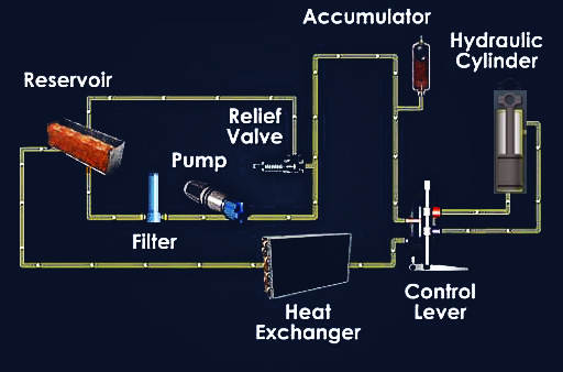
A hydraulic system is a power transmission and control system that uses pressurized fluid as the working medium,Its workflow requires the orderly coordination of various components.
◆ Electric Motor starts the process by driving the hydraulic pump.
◆ The pump draws hydraulic oil from the reservoir and pressurizes it.
◆ The pressurized oil flows through hydraulic lines to control and actuator components.
◆ Control valves determine the direction and flow rate of the oil.
◆ Actuators convert hydraulic energy into mechanical power to perform work.
Basic Working Principle: Pascal's Law
Hydraulic systems operate based on Pascal's Law, which states:
"In a confined fluid, any pressure applied is transmitted equally in all directions."
This means that when pressure is applied to a confined liquid, it is distributed evenly throughout the fluid and against the walls of the container—without any loss—allowing for efficient and controlled power transmission.
Types of Hydraulic Systems: Open Loop vs Closed Loop
A hydraulic system is a power transmission and control system that uses liquid as the working medium,Hydraulic systems can be categorized into two main types: open loop and closed loop systems.
The key difference lies in whether the fluid returns to the reservoir between the control valve and the actuator.
Closed Loop Hydraulic System
In a closed loop system, hydraulic fluid circulates continuously between the pump and the actuator, without returning to the reservoir during each cycle.
This design enables high control precision, fast response, and energy efficiency.
Common Applications of Closed Loop Systems:
Aircraft flight control systems
High-precision CNC machine tools
Servo-controlled injection molding machines
Open Loop Hydraulic System
In an open loop system, the fluid flows from the actuator back to the reservoir, and then from the reservoir to the pump via the directional control valve.
This type of system features simple construction, is easy to maintain, and is well-suited for heavy-duty applications.
Common Applications of Open Loop Systems:
Excavators
Wheel loaders
Hydraulic lifting platforms
Overall, open loop hydraulic systems are suitable for applications that require simple structure and high-power, heavy-duty performance; while closed loop hydraulic systems are ideal for applications that demand high control precision, fast response, and energy efficiency.
Advantages of Hydraulic Power Transmission vs Pneumatics
A hydraulic system is a power transmission and control system that uses liquid as the working medium,Compared to pneumatic drive, it has the following advantages:
◆ Higher Power Transmission Capability.
◆ Ideal for applications requiring high force and torque.
◆ Smooth and Continuous Speed Control.
◆ Allows for gradual, accurate movements without jerking.
◆ Large Force with Precise Control.
◆ Enables fine control over heavy loads and machinery.
Disadvantages:
◆ The response speed is not as fast as that of pneumatic systems.
◆ The system is more complex, with higher maintenance difficulty and cost.
◆ The working fluid has risks of leakage and contamination.
Applications of Industrial Hydraulic Systems
A hydraulic system is a power transmission and control system that uses pressurized liquid as the hydraulics'working medium,Can leverage its unique advantages in different application fields.
◆ Construction Equipment
◆ Industrial Automation
◆ Aerospace
◆ Manufacturing & Heavy Industry
Summary
Hydraulic systems consist of five essential hydraulic components that use pressurized fluid to perform tasks and is most commonly used in heavy-duty equipment,However, the safe delivery of hydraulic media requires effective sealing of hydraulic fittings.Any system that uses pressurized, incompressible hydraulic fluid to transmit energy is considered a hydraulic system.
According to Pascal's Law, hydraulic systems enable the conversion of mechanical energy into hydraulic energy, which can then be transformed back into mechanical energy to perform useful work they can be applied in many fields about Industrial or engineering environments with high loads, large torque, and precise control.


